Brushless hand-held tool

A technology for tools and brush hands, which is applied in the field of brushless hand-held tools, can solve the problems of loose and cracked control lines, easy failures, poor contact, etc., and achieve the effect of meeting the requirements of rapid cooling, ensuring normal use, and reliable performance

Inactive Publication Date: 2009-09-09
姜卫亮 +1
View PDF0 Cites 0 Cited by
  • Summary
  • Abstract
  • Description
  • Claims
  • Application Information

AI Technical Summary

Problems solved by technology

[0002] Existing brushless hand-held tools include a tool body, a brushless motor installed in the tool body, and a driver connected to the brushless motor. The tool body is generally small in size for the convenience of hand-holding, and the current driver uses a common circuit board. And the drive circuit makes the volume relatively large. It is difficult to assemble into the tool body without changing the volume. It can only be installed outside the tool body. The driver is connected to the brushless motor through the control line to control the work of the brushless motor. The connected control wire is also located outside the tool body. During use, the connected control wire is often pulled and cracked due to work needs, resulting in poor contact, and it is difficult for the driver to control the operation of the motor. It is inconvenient to use and prone to failure

Method used


Image

  • Brushless hand-held tool
  • Brushless hand-held tool
  • Brushless hand-held tool

Examples


Embodiment Construction

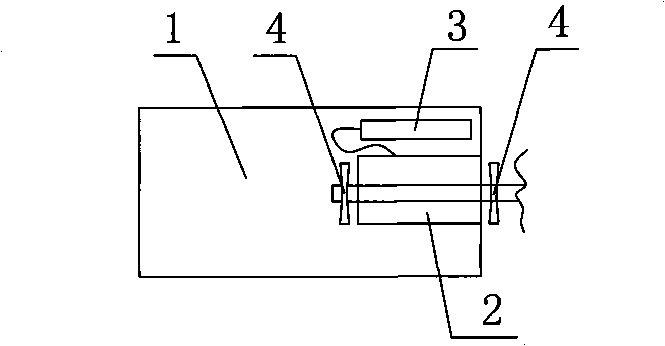
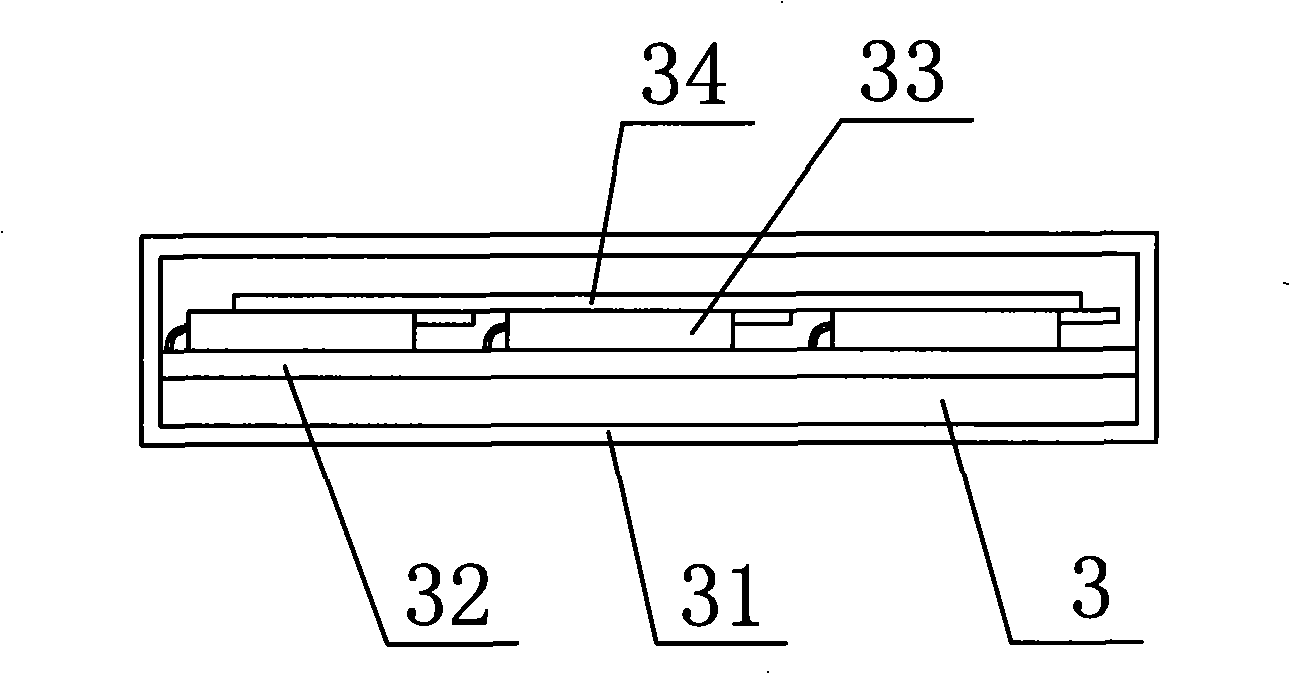
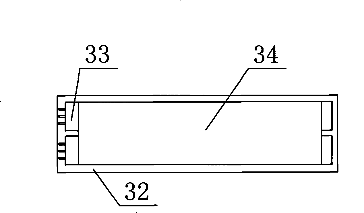
[0017] Such as Figure 1 to Figure 4 , a brushless hand-held tool, including a tool body 1, a brushless motor 2 installed in the tool body 1, a driver 3 connected to the brushless motor 2, and the driver 3 is arranged inside the tool body 1. The driver 3 includes a driver body 31 and a circuit board 32 disposed in the driver body 31 . The circuit board 32 is provided with a plurality of horizontally placed MOS tubes 33 , and a cooling fin 34 is stacked on the MOS tubes 33 . The horizontal setting of the MOS tube 33 reduces the volume of the circuit board 32, and correspondingly reduces the volume of the driver 3, so that the driver 3 can be directly arranged in the tool body 1, preventing the control line between the driver 3 and the brushless motor 2. Poor contact due to loosening and cracking caused by external pulling. The circuit board 32 includes a control chip 321 and a driving unit 322, and the driving unit 322 uses an integrated circuit to drive the chip. The integra...


PUM


Abstract

The invention provides a brushless hand-held tool, comprising a tool main body, a brushless electric motor arranged inside the tool main body, and a driver connected with the brushless electric motor and arranged inside the tool main body. The brushless hand-held tool can prevent the wire between a controller and the brushless electric motor from loosening and cracking caused by external pulling so as to be in poor contact; the brushless hand-held tool is convenient in use and reliable in performance.

Description

technical field [0001] The invention relates to a hand-held tool, in particular to a brushless hand-held tool. Background technique [0002] Existing brushless hand-held tools include a tool body, a brushless motor installed in the tool body, and a driver connected to the brushless motor. The tool body is generally small in size for the convenience of hand-holding, and the current driver uses a common circuit board. And the drive circuit makes the volume relatively large. It is difficult to assemble into the tool body without changing the volume. It can only be installed outside the tool body. The driver is connected to the brushless motor through the control line to control the work of the brushless motor. The connected control wire is also located outside the tool body. During use, the connected control wire is often pulled and cracked due to work needs, resulting in poor contact, and it is difficult for the driver to control the operation of the motor. It is inconvenient ...

Claims


Application Information

Patent Timeline
Patent Type & Authority Applications(China)
IPC IPC(8): B25F5/00
Inventor 姜卫亮应时立
Owner 姜卫亮
Why Eureka
Try Eureka