
Air generating mechanism for pre-network devices for polyamide composite filaments

A polyester-nylon compounding and pre-network technology, which is applied in the direction of pumping device, filament generation, filament/thread forming, etc., can solve the problems of high energy consumption, waste, and unfavorable saving of electric energy in the gas production mechanism, and achieve the goal of reducing equipment investment Effect

Inactive Publication Date: 2009-09-09
常熟市海欣复合材料有限公司
View PDF0 Cites 3 Cited by
  • Summary
  • Abstract
  • Description
  • Claims
  • Application Information

AI Technical Summary

Problems solved by technology

However, the gas used in the polyester / nylon composite filament pre-network device, that is, the network gas, is the opposite, that is, there is no strict requirement on the gas pressure, but the gas supply is very particular. If the gas supply is small, it will affect pre-network effects
If a large-scale or large-capacity gas generating mechanism is used in order to increase the gas supply, on the one hand, it will cause an increase in investment, and on the other hand, it will also cause waste. The so-called waste phenomenon refers to the energy consumption of the gas generating mechanism. Big
For example, if the configuration is 20m 3 / min of the above-mentioned structure of the gas generating mechanism will cause waste, which is not conducive to saving electric energy; on the contrary, if the configuration is 6m 3 The gas generating mechanism of the above-mentioned structure of / min then can cause the insufficient gas producing capacity again and can't guarantee the normal function of pre-network device to play, therefore it is necessary to make reasonable improvement to the gas generating mechanism in the prior art, make it save energy To find a balance between meeting the gas supply requirements of the network gas, the technical solution to be introduced below is based on this background

Method used


Image

  • Air generating mechanism for pre-network devices for polyamide composite filaments
  • Air generating mechanism for pre-network devices for polyamide composite filaments

Examples


Embodiment Construction

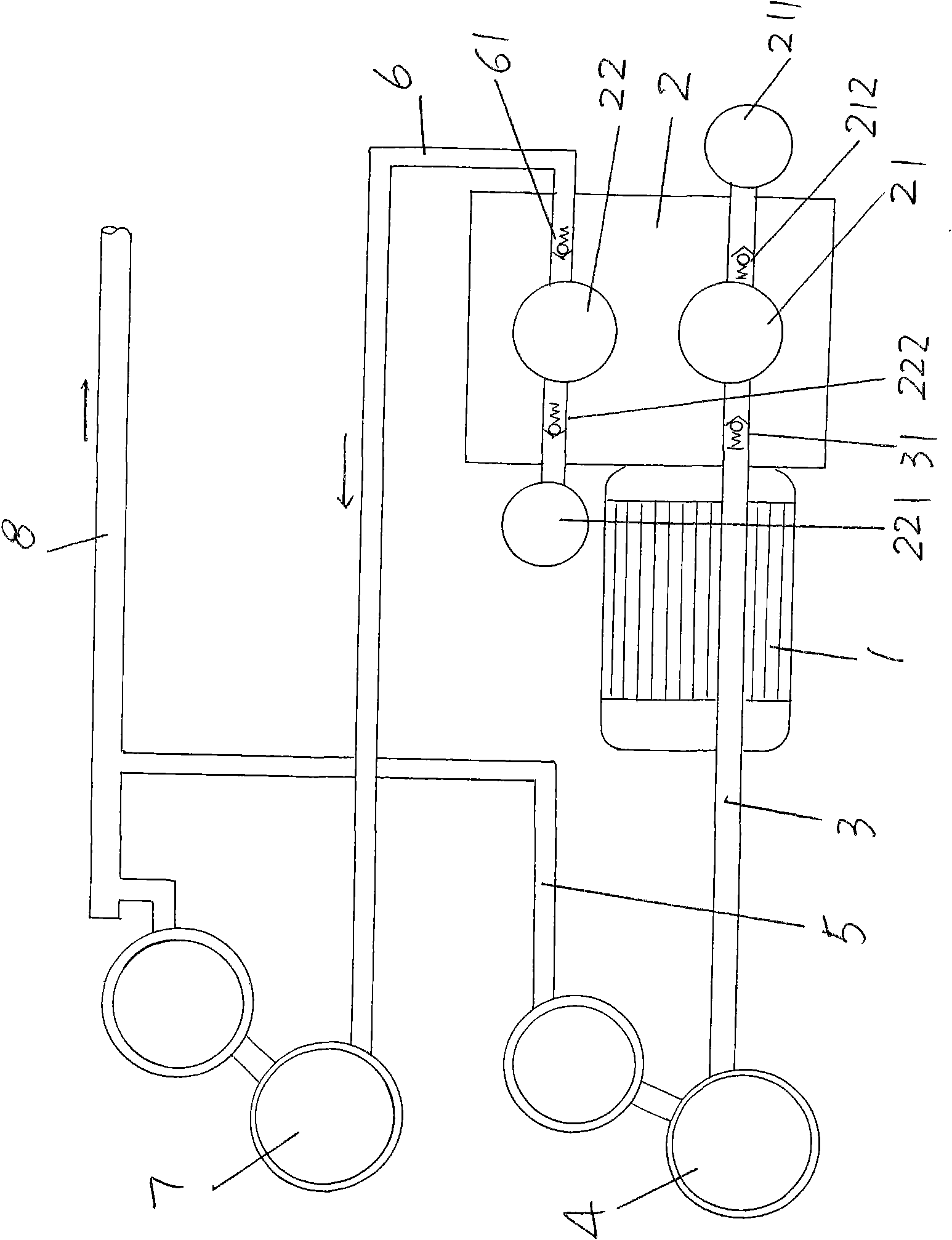
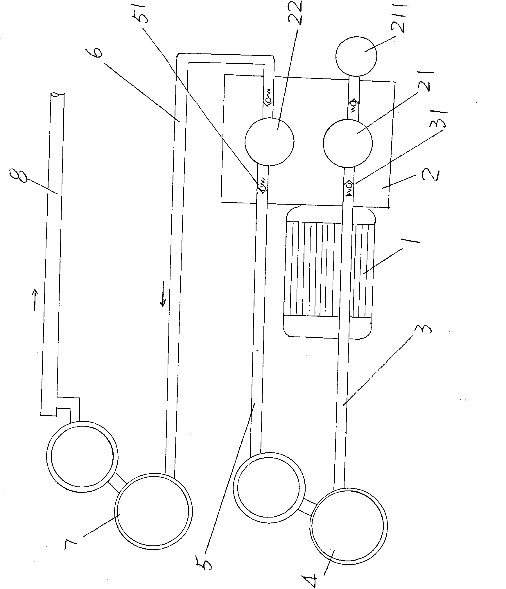
[0010] please see figure 1 , the gas generating mechanism given is essentially a piston air compressor, the motor 1 is matched with the piston compressor 2, the piston compressor 2 has first and second cylinders 21, 22, and the first cylinder 21 is A first air filter element 211 is provided on the air port, and a first intake valve 212 is provided on the channel of the intake port of the first cylinder 21, and the first intake valve 212 is a one-way valve. A second air filter element 221 is provided on the intake port of the second cylinder 22, and a second intake valve 222 is provided on the passage of the intake port of the second cylinder 22, and the second intake valve 222 is a one-way valve. . One end of the first air outlet pipe 3 is connected to the piston compressor 2 and communicated with the first cylinder 21, the passage of the first air outlet pipe 3 is provided with a first air outlet valve 31, the first air outlet pipe 3 The other end is connected to the first...


PUM


Abstract

The invention relates to an air generating mechanism for pre-network devices for polyamide composite filaments, belonging to the technical field of pre-network devices for polyamide composite filaments. The air generating mechanism comprises a motor, a piston compressor, a first air outlet pipe, an air inlet pipe and a second air outlet pipe, wherein the piston compressor is matched and connected with the motor; one end of the first air outlet pipe is communicated with a first air cylinder of the piston compressor, and the other end of the first air outlet pipe is communicated with a first air holder; one end of the air inlet pipe is connected with the head of the first air holder, and the other end of the air inlet pipe is connected with a third air outlet pipe; one end of the third air outlet pipe is connected with a second air holder, and the other end of the third air outlet pipe is connected with a pre-network device; and one end of the second air outlet pipe is communicated with a second air cylinder of the piston compressor, and the other end of the second air outlet pipe is connected with the second air holder. The air generating mechanism can meet the air supply requirements of low pressure and large air supply quantity needed by the pre-network device, and not only can reduce the equipment investment but also can save energy.

Description

technical field [0001] The invention belongs to the technical field of a polyester-nylon composite filament pre-network device, and in particular relates to a gas-generating mechanism for a polyester-nylon composite filament pre-network device. Background technique [0002] The applicant has overcome the technical prejudice in the prior art, and has improved the traditional spinning mode generally believed in the industry without carrying out pre-networking of polyester-nylon composite filaments, that is, in the complete spinning device of polyester-nylon composite filaments A pre-network device is added on the above, more specifically, a pre-network device is set between the spinning box and the winder with the winder as a carrier, and the silk spun by the spinning box is set by the pre-network device. The side blowing device in the spinning box performs side blowing, cooling by the cooling device and oiling by the oiling device while pre-internetting is performed. The so-c...

Claims


Application Information

Patent Timeline
Patent Type & Authority Applications(China)
IPC IPC(8): D01D13/02D01D5/096D01D11/00F04B35/04F04B41/02
Inventor 钱燕飞张文如顾金荣
Owner 常熟市海欣复合材料有限公司
Learn More