Method for driving solenoid-operated fuel injector in diesel

A fuel injector, fuel injection technology, applied in the direction of fuel injection device, fuel injection control, internal combustion piston engine, etc.

Inactive Publication Date: 2009-09-09
GM GLOBAL TECH OPERATIONS LLC
View PDF6 Cites 6 Cited by
  • Summary
  • Abstract
  • Description
  • Claims
  • Application Information

AI Technical Summary

Problems solved by technology

[0012] Another problem may arise with the method according to the prior art,

Method used


Image

  • Method for driving solenoid-operated fuel injector in diesel
  • Method for driving solenoid-operated fuel injector in diesel
  • Method for driving solenoid-operated fuel injector in diesel

Examples


Embodiment Construction

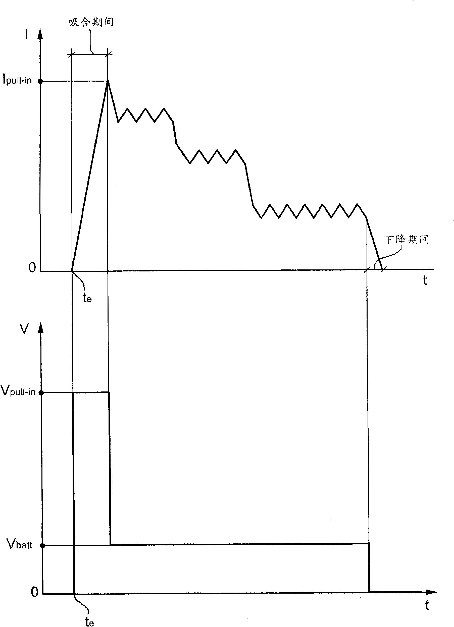
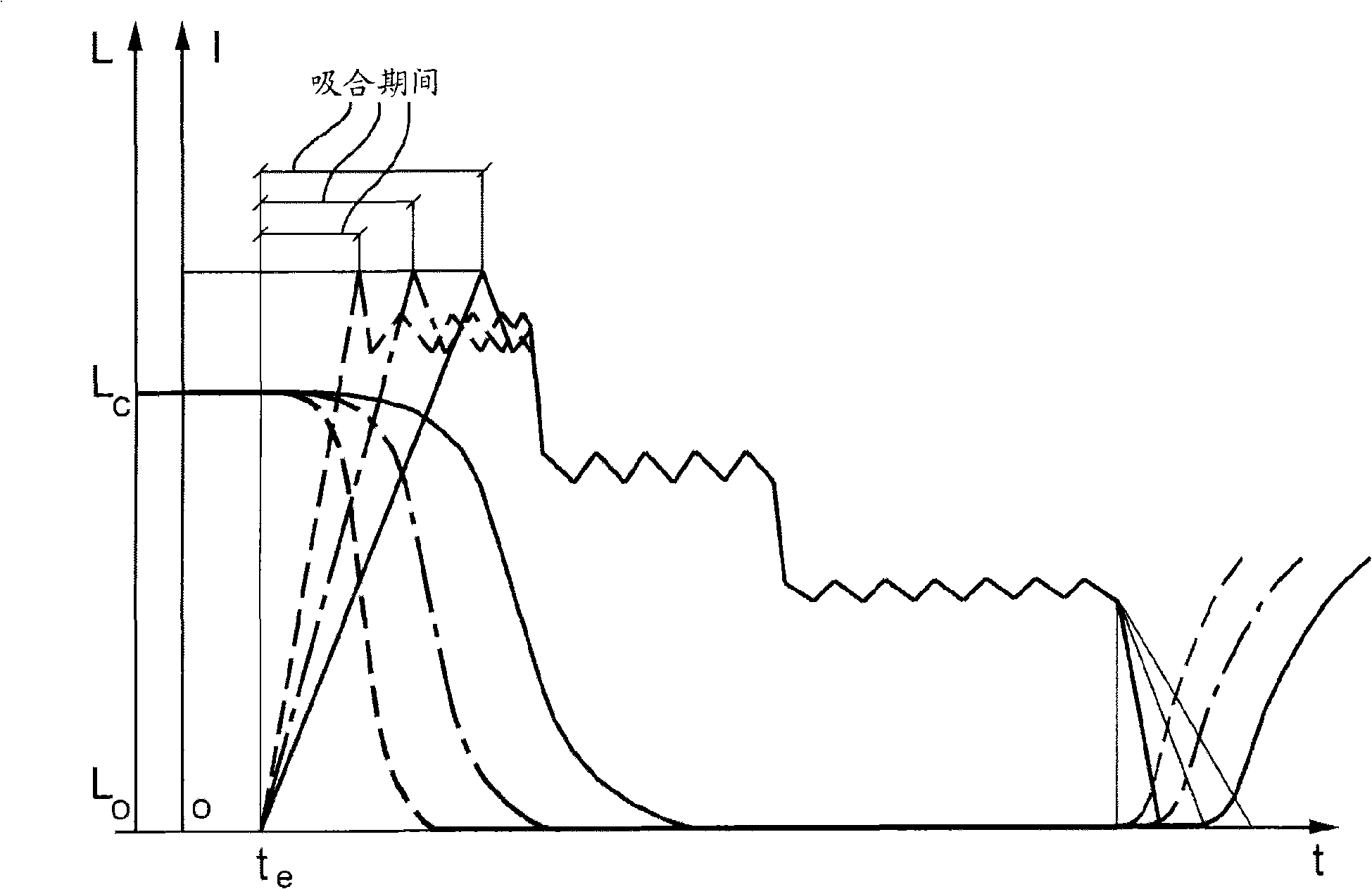
[0021] In a first embodiment, the method according to the invention is basically based on monitoring the actual value of the pull-in voltage: when said actual value of the voltage is lower than the expected value, i.e. lower than the predetermined nominal value, the injection start time and The solenoid energization time is modified to at least partially compensate for deviations in the actual value of the pull-in voltage from the nominal value. In particular, the injection start time (or corresponding crank angle value) is predicted relative to the nominal injection time by an amount substantially proportional to the decrease in the sensed pull-in voltage, and the solenoid energization time ET is increased relative to its nominal value Basically proportional to the amount of reduction in pull-in voltage.

[0022] In general, the functional relationship between the reduction of the pull-in voltage, the corresponding advance of the injection start time and the increase of the s...


PUM


Abstract

The present invention relates to a method for a driving solenoid-operated fuel injector in diesel. An accurate control of a solenoid-operated fuel injector in a Diesel or gasoline engine requires that a pull-in voltage (V pull-in ) higher than the generally available battery voltage (V batt ) is applied to the injector (2,3), and that the injection is ended as quickly as possible, in order that the fuel injection closely follows the solenoid current profile. When the initial pull-in voltage is lower than the expected nominal value, a deviation of the injected fuel quantity appears with respect to the nominal quantity. This inconvenience is overcome by monitoring the actual value of a selected parameter, such as the actual value of the initial pull-in voltage (V pull-in), and the injectionstart time (t e ) and the solenoid energizing time (ET) are correspondingly modified ( t, ET).

Description

technical field [0001] The invention relates to fuel injection for internal combustion engines. [0002] More specifically, the present invention relates to methods for driving solenoid actuated fuel injectors. Background technique [0003] Control systems and methods for fuel injectors for internal combustion engines are well known in the art, eg from US-A-4459670, US-A-4355619 and EP-A-0114378. [0004] A conventional solenoid fuel injector has a solenoid actuator and includes a valve housing with a current coil and electrical connections, and a valve seat with a nozzle and a movable valve needle. When such an injector is energized, that is, when current is supplied to the solenoid actuator, the coil generates a magnetic field that lifts the valve needle off its seat, allowing fuel to flow through the injector and out of the nozzle for injection. to the combustion chamber of the corresponding cylinder. When the injector is de-energized, ie, current is no longer supplied...

Claims


Application Information

Patent Timeline
IPC IPC(8): F02D41/30F02M51/00G05B15/00
CPCF02D41/40F02D2041/2003Y02T10/44F02D41/402F02D2041/2051F02D2041/1432F02D2041/2058F02D41/20Y02T10/40
Inventor 保罗·卡萨索
Owner GM GLOBAL TECH OPERATIONS LLC
Why Eureka
Try Eureka