Unidirectional clutch type stepless speed change device for off-road motor vehicles

A continuously variable transmission device and motor vehicle technology, which is applied in transmission devices, mechanical equipment, belts/chains/gears, etc., can solve the problems of shoe wear life, unfavorable manufacturing, high cost, etc., and achieve high torque transmission efficiency and structure Simple and reasonable, convenient operation and maintenance

Inactive Publication Date: 2009-09-09
胡济荣
View PDF0 Cites 3 Cited by
  • Summary
  • Abstract
  • Description
  • Claims
  • Application Information

AI Technical Summary

Problems solved by technology

[0003] 1. The engine has a built-in wet clutch and continuously variable transmission separation structure. In order to achieve downhill engine braking, a one-way bearing for braking will be added. This structure is huge and bloated, which is not conducive to the overall shape design of non-motor vehicles. At the same time, the machining accuracy and service life of the clutch and one-way bearing are very high, which is not conducive to production and manufacturing, and the cost is extremely high
[0004] 2. The centrifugal shoe clutch is combined with the continuously variable transmission mechanism, which is mainly used for two-wheeled motorcycles. This structure is also relatively large, and there is no anti-drag braking function of the engine, so it cannot be used for all-terrain four-wheel vehicles.
Moreover, because the torque is transmitted by the friction of the outer surface of the shoe, it is easy to slip and generate heat during the acceleration and deceleration process, and the wear life of the shoe is also a serious problem.
Especially the driven wheel assembly, as long as the engine is started, the belt is always rotating, which accelerates the wear of the belt and reduces the service life of the engine
For this reason, many manufacturers and people of insight have carried out research and development at the above-mentioned problems, but there is no ideal product on the market so far.

Method used


Image

  • Unidirectional clutch type stepless speed change device for off-road motor vehicles
  • Unidirectional clutch type stepless speed change device for off-road motor vehicles
  • Unidirectional clutch type stepless speed change device for off-road motor vehicles

Examples


Embodiment Construction

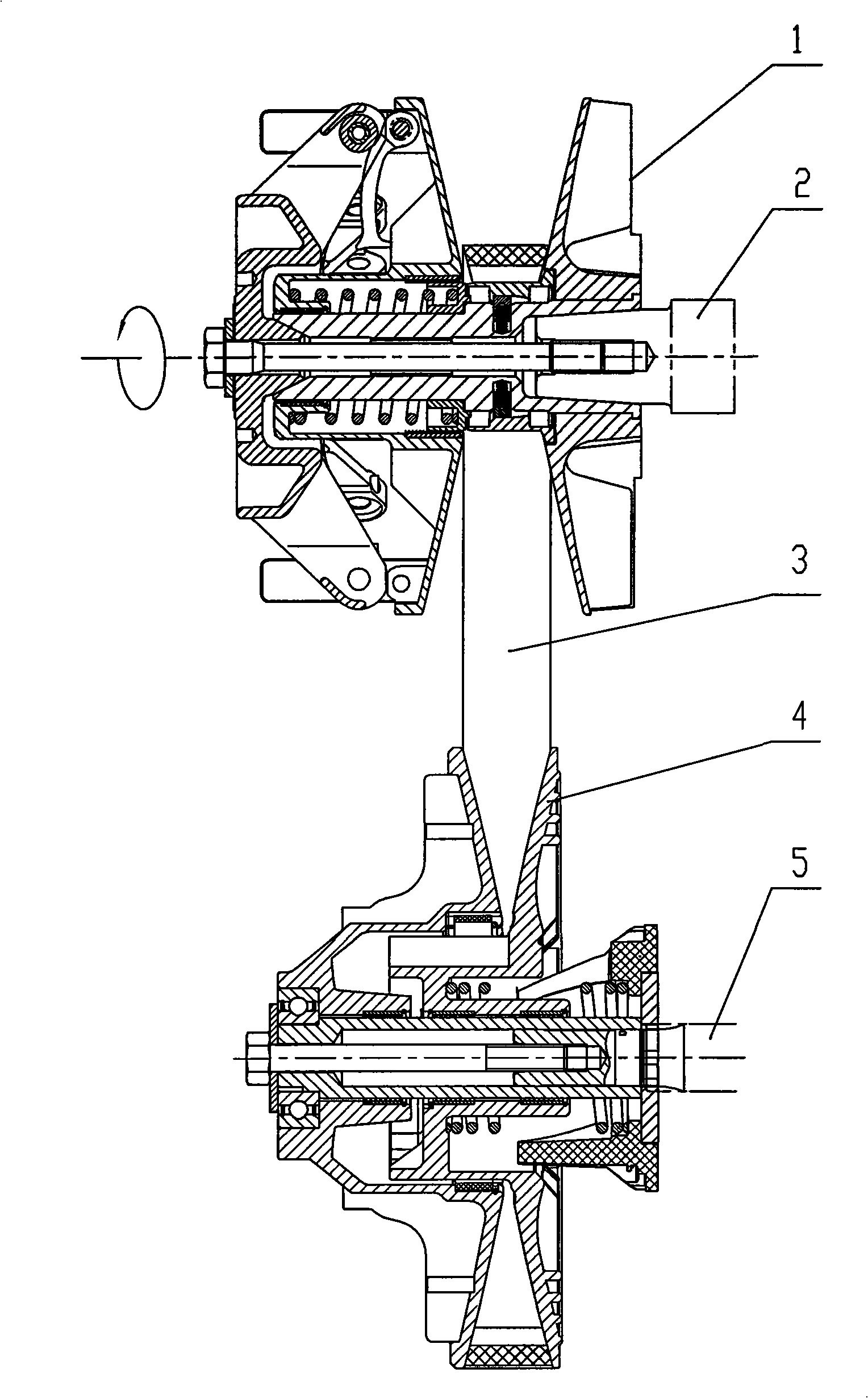
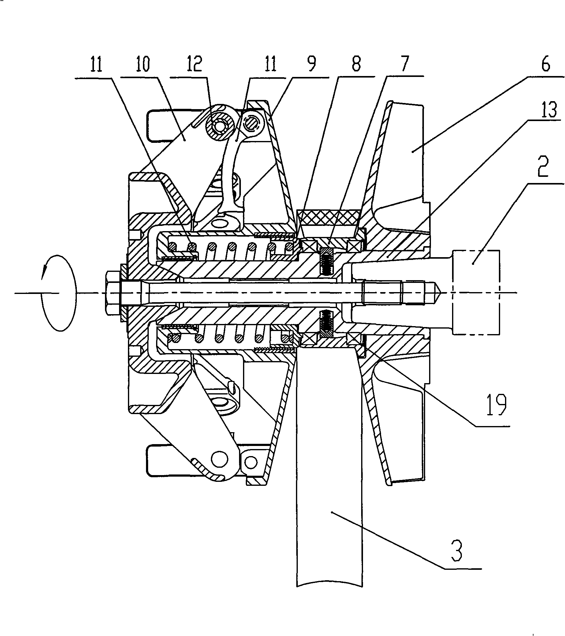
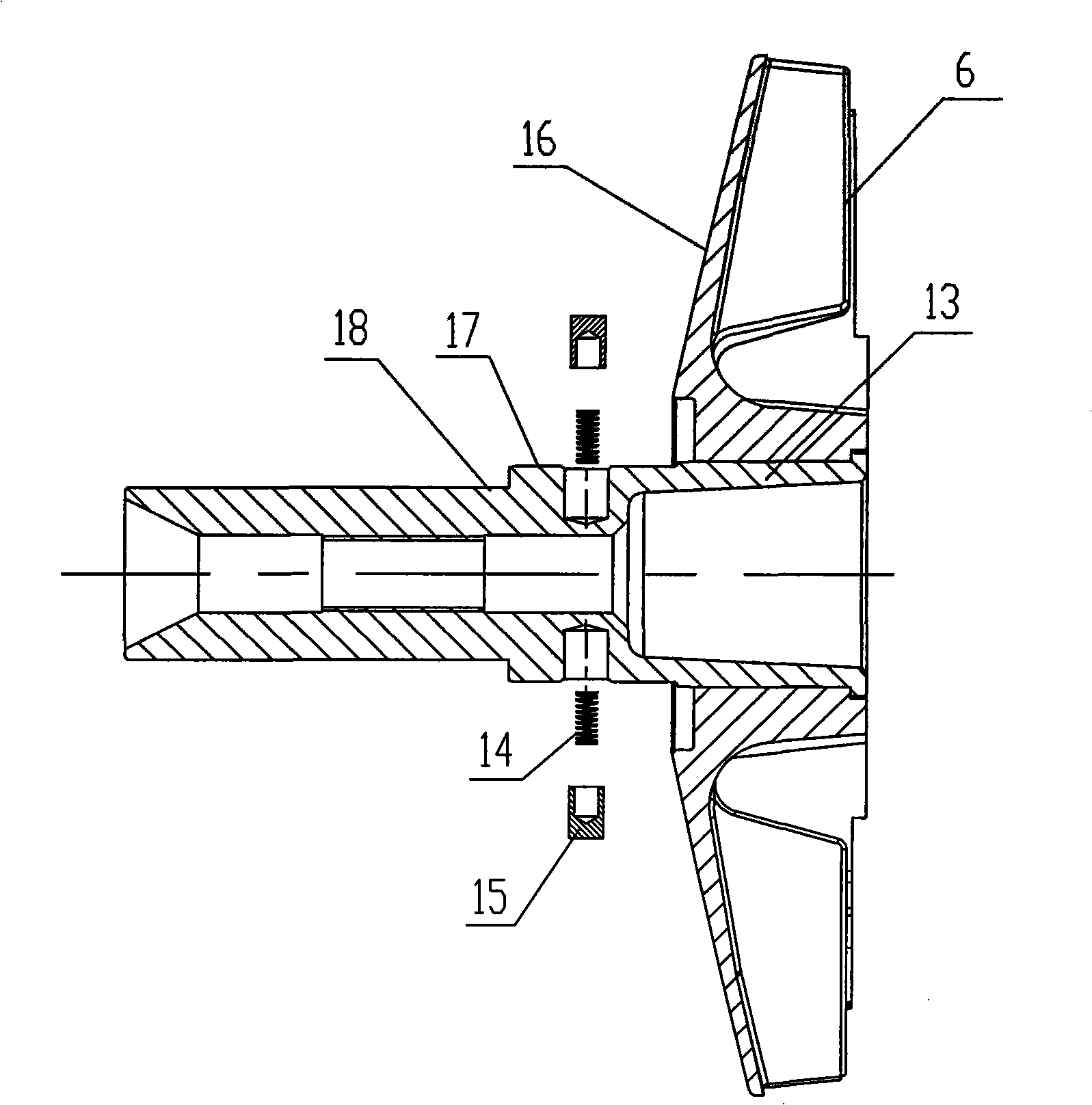
[0019] Figure 1 to Figure 6 As shown, the present invention creates a specific embodiment of the one-way clutch type continuously variable transmission device for non-road motor vehicles, which includes a driving wheel assembly 1 arranged on an input shaft 2, a driven wheel assembly 4 arranged on an output shaft 5, The driving wheel assembly 1 is connected with the driven wheel assembly 4 through the belt 3, and the driving wheel assembly 1 includes a pulley 6, an axle 13, a sliding sleeve 7, a spring seat 8, a pressure pulley 9, a driving wheel spring 11, a supporting wheel 10, The pulley 6 is fixed on the wheel shaft 13, the sliding sleeve 7, the spring seat 8, and the pressure pulley 9 are sequentially movably sleeved on the wheel shaft 13 and axially positioned by the support wheel 10, and the sliding sleeve 7 is arranged on the sliding sleeve mating surface 17 of the wheel shaft 13 Above, the spring seat 8 is arranged on the spring seat mating surface 18 of the wheel sha...


PUM


Abstract

The invention discloses a unidirectional clutch type stepless speed change device for off-road motor vehicles, comprising a driving wheel component (1), a driven wheel component (4), a belt (3); the driving wheel component (1) comprises a pulley (6), an axle (13), a sliding sleeve (7), a spring seat (8), a pressure roller (9), a driving wheel spring (11), a supporting wheel (10); wherein, the sliding sleeve (7), the spring seat (8) and the pressure roller (9) are sheathed on the axle (13) and are positioned by the supporting wheel (10), the driving wheel spring (11) is arranged between the spring seat (8) and the pressure roller (9); the inner surface of the sliding sleeve (7) is provided with spiral grooves (22), spiral guide surfaces (21) facilitate the transition between two spiral grooves, the axle (13) is provided with pin springs (14) and pins (15), the pins (15) are contacted with the spiral grooves (22) of the sliding sleeve (7). With the structure adopted, the unidirectional clutch type stepless speed change device has the characteristics of simple and reasonable structure, reliable performance and small volume, high integrity and convenient operation and maintenance.

Description

technical field [0001] The invention relates to a transmission device, in particular to a one-way clutch type continuously variable transmission device for non-road motor vehicles. Background technique [0002] At present, there are two main types of clutches and continuously variable transmission composite structures used in non-road motor vehicles: the combination of the built-in wet clutch in the engine and the continuously variable transmission separation structure, and the combination of the centrifugal shoe clutch and the continuously variable transmission mechanism. The structure has the following disadvantages during use: [0003] 1. The engine has a built-in wet clutch and continuously variable transmission separation structure. In order to achieve downhill engine braking, a one-way bearing for braking will be added. This structure is huge and bloated, which is not conducive to the overall shape design of non-motor vehicles. At the same time, the machining accuracy...

Claims


Application Information

Patent Timeline
Patent Type & Authority Applications(China)
IPC IPC(8): F16H9/10F16H35/00
Inventor 胡济荣
Owner 胡济荣
Why Eureka
Try Eureka