Gas flow control valve

A technology for flow control valves and gas, applied in sliding valves, valve details, safety valves, etc., can solve problems such as inconvenient use, unsafety, and insufficient gas supply

Inactive Publication Date: 2009-09-09
GRAND MATE
View PDF0 Cites 0 Cited by
  • Summary
  • Abstract
  • Description
  • Claims
  • Application Information

AI Technical Summary

Problems solved by technology

[0003] However, in terms of gas flow control in this case, it is limited by the diameter of the flow control holes and there are only several fixed flow control options; in other words, the diameter of the flow control holes can only be adjusted in stages The gas flow rate cannot be adjusted in a linear manner; on the whole, this case does not necessarily meet the needs of users in use, and it is inconvenient to use
Furtherm...

Method used


Image

  • Gas flow control valve
  • Gas flow control valve
  • Gas flow control valve

Examples


Embodiment Construction

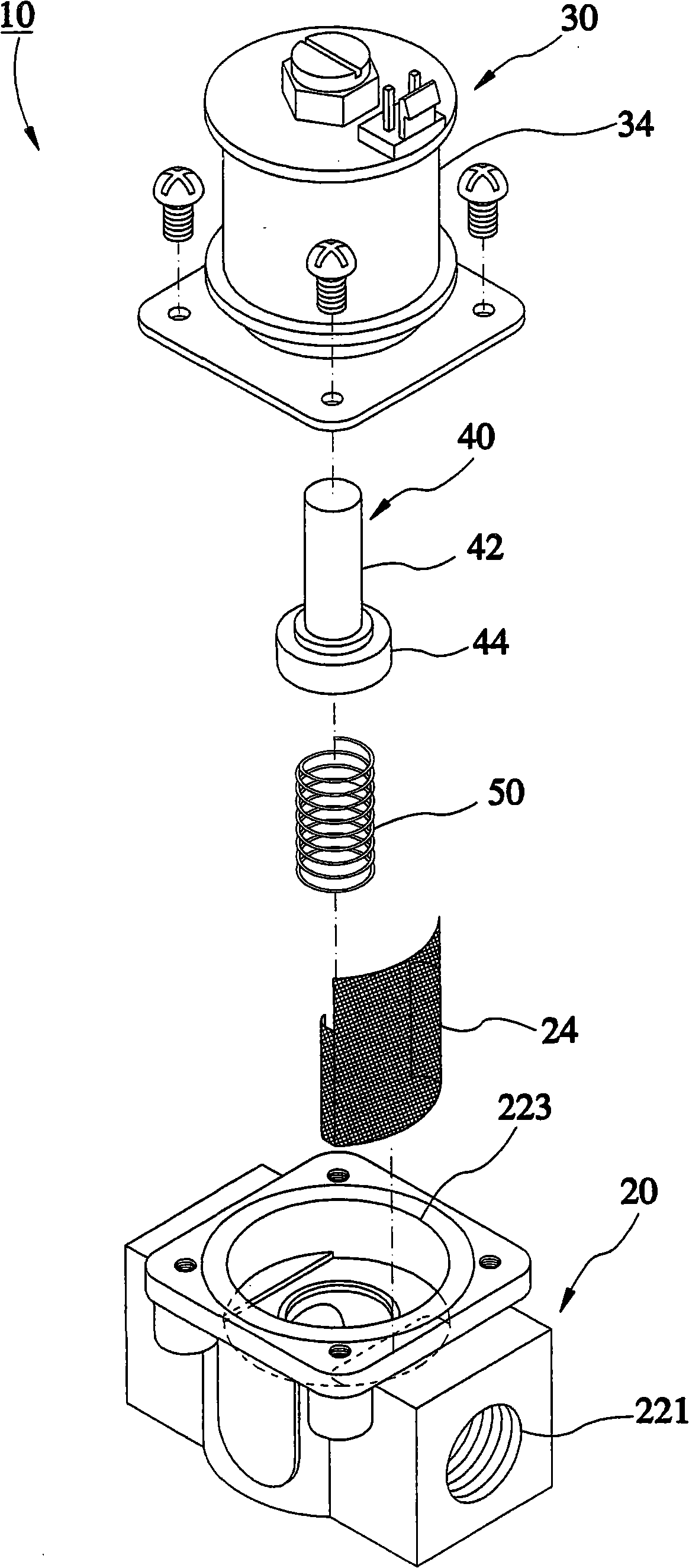
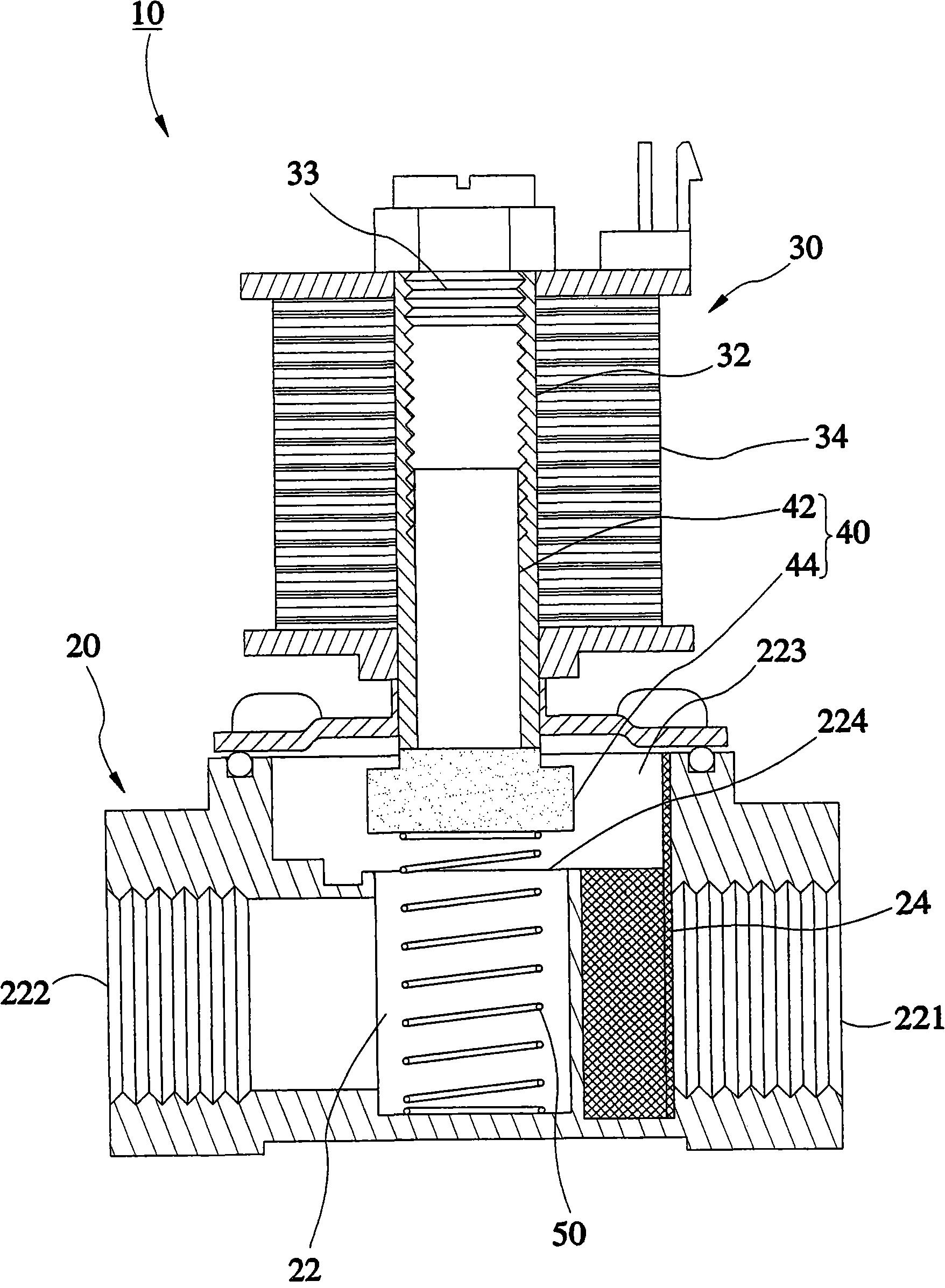
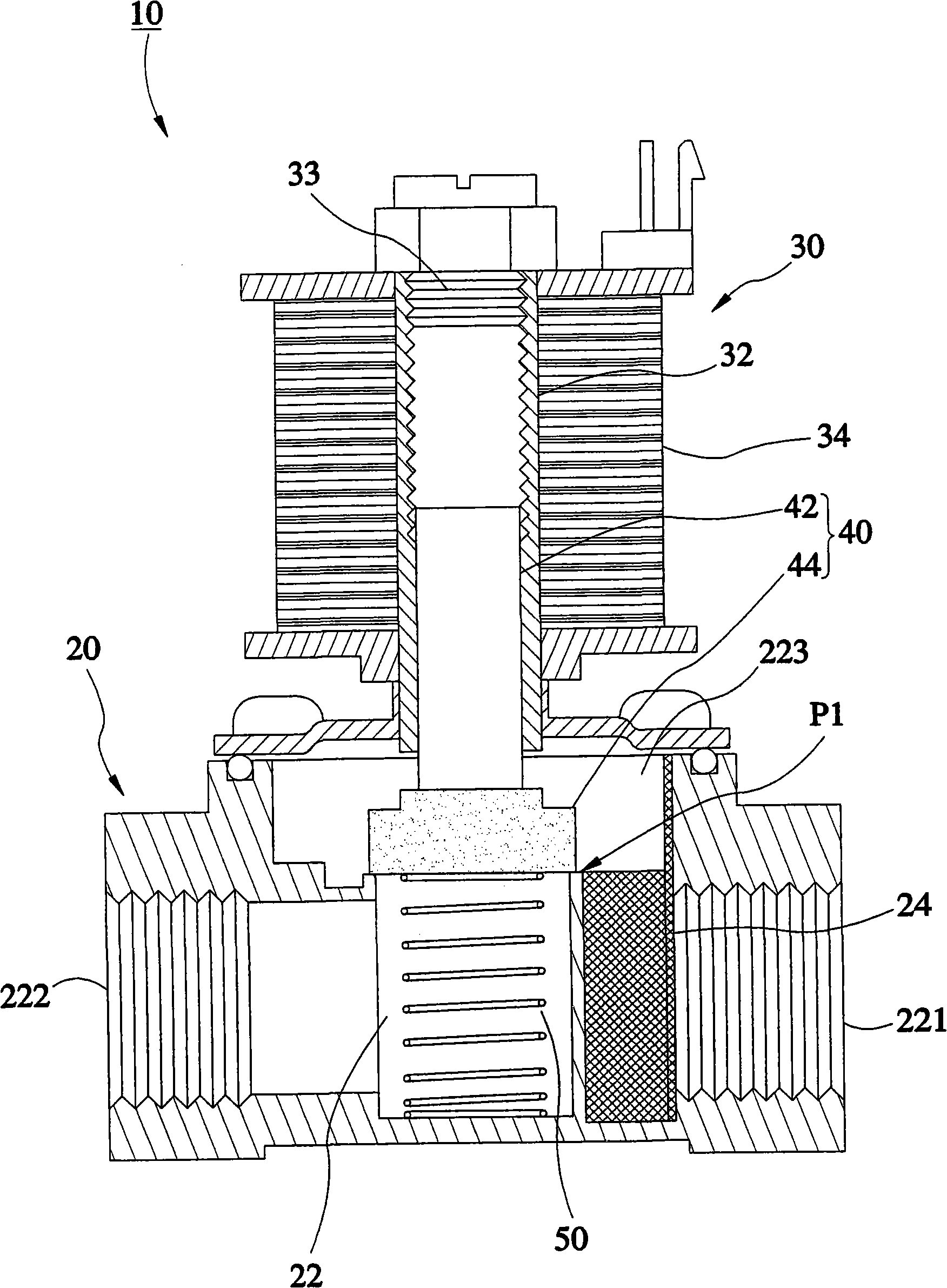
[0036] see Figure 1 to Figure 3 , which is a gas flow control valve 10 provided in the first preferred embodiment of the present invention, including: a lower valve seat 20 , an upper valve seat 30 , a magnetic column set 40 and a spring 50 .

[0037] The lower valve seat 20 has a flow channel 22 inside for the passage of gas; the flow channel 22 forms an inlet 221, an outlet 222 and a through hole 224 between the inlet 221 and the outlet 222 on the lower valve seat 20, And an opening 223 above the through hole 224; the inlet 221 is used for gas to flow into the lower valve seat 20; the outlet 222 is used for outputting gas; the opening 223 communicates with the middle section of the flow channel 22 and is located at the top of the lower valve seat 20 Through this, under normal passage, the gas can enter the opening 223 from the inlet 221 and then go from the through hole 224 to the outlet 222 . The lower valve seat 20 further includes a filter screen 24, which is located in...


PUM


Abstract

The invention provides a gas flow control valve, which comprises a lower valve seat having a flow passage for supplying gas; an upper valve seat is fixed on the top of the lower valve seat and has a pipe body and an electromagnetic coil group sleeved outside the pipe body; the pipe body is communicated with the flow passage; the electromagnetic coil group can generate a magnetic field after being powered; a magnetic cylinder group has a magnetic part and a sealing part, the magnetic part is a permanent magnet inserted into the pipe body and the magnetic part makes the magnetic cylinder group move along the axial direction of the pipe body under the action of the magnetic field of the electromagnetic coil group; when the magnetic cylinder group moves, the sealing part changes the proportion of the covered cross section of the flow passage correspondingly to control the flow of the gas passing through the flow passage; and a spring is arranged on one the top and bottom sides of the magnetic cylinder group and is positioned in the axial direction of the magnetic cylinder group for providing acting force for the balance and positioning of the magnetic cylinder group.

Description

technical field [0001] The invention relates to a gas appliance, in particular to a gas flow control valve. Background technique [0002] Such as China Taiwan Patent No. M322516 patent case [gas flow switch control valve], the feature of this case is: the gas flow switch control valve has a rotary gas supply flow limiting disc and a fixed gas supply flow limiting circle The gas flow is controlled by the disk; the rotary air supply flow limiting disk has a plurality of flow control holes with different apertures, and the fixed air supply flow limiting disk has a guide hole. When the guide hole selectively corresponds to the One of the flow control holes can be used for gas to pass through; among them, in this case, the area of ​​the flow channel is changed through the size of the different flow control holes, so as to achieve the purpose of changing the gas flow. [0003] However, in terms of gas flow control in this case, it is limited by the diameter of the flow control ho...

Claims


Application Information

Patent Timeline
IPC IPC(8): F16K3/24F16K31/02F16K17/36
Inventor 黄锦颖黄信铭颜忠圣
Owner GRAND MATE
Why Eureka
Try Eureka