
Temperature self-compensation fiber grating displacement sensor

A technology of displacement sensor and optical fiber grating, which is applied in thermometers, optical devices to transmit sensing components, and thermometers with physical/chemical changes. , measurement signal instability and other problems, to achieve the effect of simple structure, good long-term stability and large measuring range

Inactive Publication Date: 2009-09-09
SOUTHEAST UNIV
View PDF0 Cites 37 Cited by
  • Summary
  • Abstract
  • Description
  • Claims
  • Application Information

AI Technical Summary

Problems solved by technology

However, this type of displacement sensor still has certain limitations in engineering applications. For example, the electrical displacement sensor is susceptible to electromagnetic interference, the measurement signal is unstable, and the vibrating wire displacement sensor will produce creep and poor long-term stability when used for a long time.

Method used


Image

  • Temperature self-compensation fiber grating displacement sensor
  • Temperature self-compensation fiber grating displacement sensor
  • Temperature self-compensation fiber grating displacement sensor

Examples


Embodiment Construction

[0022] The technical scheme of the present invention is described in detail below in conjunction with accompanying drawing:

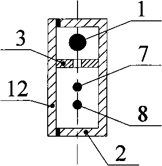
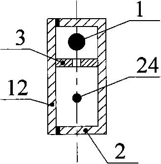
[0023] Such as Figure 1 to Figure 10 As shown, the temperature self-compensating fiber grating displacement sensor of the present invention includes a probe 1, a metal box 2, a partition 3, a connecting rod 4, a limit plate 5, a first pigtail 6, a left spring 7, a second pigtail 8, a Three pigtails 9, right spring 10, fourth pigtail 11, metal box cover 12, guide rod hole 13, first small hole 14, left metal connection block 15, capillary metal tube 16, epoxy resin 17, right metal connection Block 18, bare fiber grating 19, partition plate long hole 22, the second small hole 23, the third small hole 24, the first fiber grating sensor 25, the second fiber grating sensor 26; wherein, the partition plate 3 is horizontally arranged in the metal box 2, the left and right ends and the bottom are fixed to the inner wall of the metal box 2, and the metal box 2 ...


PUM


Abstract

The invention provides a temperature self-compensation fiber grating displacement sensor which has a structure that two bare fiber gratings which are encapsulated by capillary metal tubes are connected with a probe through a metal connecting block, a spring and a centre rod to form a main body of the temperature self-compensation fiber grating displacement sensor to execute functions; then the main body is arranged in a metal box; finally, the end parts of the capillary metal tubes are fixed with the metal box through the metal connecting block, fibers penetrate out from small holes positioned on the metal connecting block and the lateral wall of the metal box, and the probe can freely stretch through a guide rod hole of the metal box. When a displacement sensor is arranged on the structure, the probe and the metal box relatively move to enable the bare fiber gratings to extend or shorten so as to generate the drift of the operating wavelength of the bare fiber gratings when the structure generates displacement, and the displacement and the temperature of the structure can be tested by utilizing a temperature compensation principle and a displacement computing formula of the displacement sensor.

Description

technical field [0001] The invention relates to a displacement measuring device, in particular to a sensor for measuring the displacement of civil engineering structure model tests and long-term use. Background technique [0002] At present, ordinary electrical and vibrating wire displacement sensors are installed on the structure, which can measure the displacement of the structure under various loads in the short term or in the long term, so as to analyze the force status of the structure. However, this type of displacement sensor still has certain limitations in engineering applications. For example, the electrical displacement sensor is susceptible to electromagnetic interference, the measurement signal is unstable, and the vibrating wire displacement sensor will produce creep and poor long-term stability when used for a long time. [0003] In order to develop a displacement sensor with better performance for the state measurement of the structure, it is one of the effec...

Claims


Application Information

Patent Timeline
IPC IPC(8): G01B11/02G01K11/32G01D5/26G01K11/3206
Inventor 周广东李爱群丁幼亮
Owner SOUTHEAST UNIV
Learn More