
Distributed high-precision fiber grating displacement sensor with temperature compensation and method

A displacement sensor, fiber grating technology, applied in instruments, optical devices, measuring devices, etc., can solve the problems of cumbersome packaging process, low sensitivity and uneven strain distribution of displacement sensors, achieve good market economic benefits, easy productization, The effect of high measurement accuracy

Active Publication Date: 2019-05-17
徐梦雪
View PDF5 Cites 0 Cited by
  • Summary
  • Abstract
  • Description
  • Claims
  • Application Information

AI Technical Summary

Problems solved by technology

For this reason, there are currently many displacement sensors based on fiber Bragg grating sensing technology. Most of the fiber gratings are symmetrically pasted on the upper and lower surfaces of the cantilever beam to realize displacement detection and temperature compensation, and the pasted fiber grating is susceptible to strain distribution on the surface of the cantilever beam chirp failure
For this reason, the performance of this type of FBG displacement sensor is limited by the structure of the cantilever beam and the bonding process of the FBG
At the same time, most of this type of displacement sensor has the disadvantages of cumbersome packaging process, large size and low sensitivity, and is not suitable for high-precision displacement detection.

Method used


Image

  • Distributed high-precision fiber grating displacement sensor with temperature compensation and method
  • Distributed high-precision fiber grating displacement sensor with temperature compensation and method
  • Distributed high-precision fiber grating displacement sensor with temperature compensation and method

Examples


Embodiment Construction

[0026] The present invention will be further described below in conjunction with specific examples and accompanying drawings.

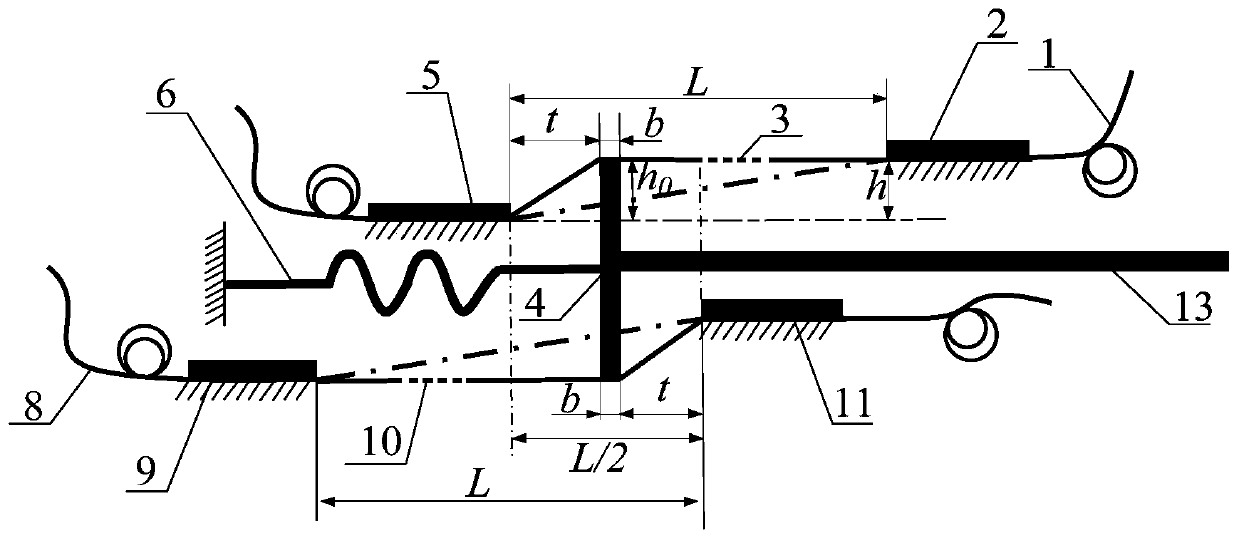
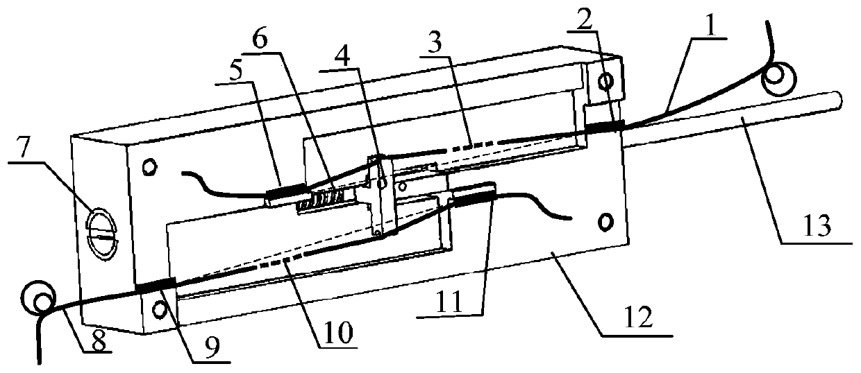
[0027] The invention provides a distributed high-precision optical fiber grating displacement sensor with temperature compensation, such as Figure 1 to Figure 6 As shown, it includes a base 12 and an optical fiber with a grating in the base 12, the optical fiber includes a first optical fiber 1 and a second optical fiber 8, the first optical fiber 1 is provided with a first grating 3, and the second optical fiber 8 is provided with a first optical fiber 8. Two gratings 10, the two ends of the first grating 3 are respectively fixed to the base 12 through the first fixed point 2 and the second fixed point 5, and the two ends of the second grating 10 are respectively passed through the third fixed point 9 and the fourth fixed point The fixing point 11 is fixed to the base 12, and the first to fourth fixing points 2, 5, 9, 11 make the first optical fiber...


PUM


Abstract

The invention provides a distributed high-precision FBG (fiber bragg grating) displacement sensor with a function of temperature compensation, and the sensor comprises a substrate, and optical fibers which are located in the substrate and are provided with optical gratings. The optical fibers comprise a first optical fiber and a second optical fiber. The first optical fiber is provided with the first optical grating, and the second optical fiber is provided with the second optical grating. The first and second optical fibers are arranged in the same plane on the substrate in an inclined, staggered and parallel manner. An optical fiber two-side loading block is disposed between the first and second optical fibers, and the first and second optical gratings are enabled to be respectively located at two sides of the optical fiber two-side loading block. The optical fiber two-side loading block is connected with a displacement loading rod, wherein one end of the displacement loading rod is led out, and the other end of the displacement loading rod is connected with the substrate through a reset spring, wherein the reset spring has a certain compression in an initial state. According to the invention, the two optical fibers which are arranged in the same plane on the substrate in the inclined, staggered and parallel manner are linked with the optical fiber two-side loading block and the displacement loading rod, and the lateral characteristics of the optical fibers are directly used, thereby effectively improving the sensitivity of the sensor and reducing the size of the sensor.

Description

technical field [0001] The invention relates to the technical field of distributed high-precision displacement detection, in particular to a distributed high-precision optical fiber grating displacement sensor with temperature compensation and a method thereof. Background technique [0002] Displacement detection is widely used in many fields, for example, it is used as an important index to evaluate the health status of structures in civil buildings such as civil engineering bridges; it can also be used as an important physical quantity for feedback control and compensation, such as in micro-nano control, precise positioning and high-precision machining and other fields. At present, electrical displacement sensing is the most widely used, mainly represented by capacitance, eddy current and inductive displacement sensing technologies. However, this type of electrical displacement sensor is vulnerable to other harsh working conditions such as electromagnetic interference, ha...

Claims


Application Information

Patent Timeline
Patent Type & Authority Patents(China)
IPC IPC(8): G01B11/02
CPCG01B11/02
Inventor 李天梁尹洁明
Owner 徐梦雪
Learn More