
Brushless electric motor rotor

A brushless motor and motor rotor technology, applied in the manufacture of stator/rotor body, magnetic circuit rotating parts, magnetic circuit shape/pattern/structure, etc. , to achieve the effect of reducing production costs and improving yield

Inactive Publication Date: 2009-09-09
姜卫亮 +1
View PDF1 Cites 10 Cited by
  • Summary
  • Abstract
  • Description
  • Claims
  • Application Information

AI Technical Summary

Problems solved by technology

[0004] The purpose of the present invention is to provide a brushless motor rotor, which can effectively solve the danger of the magnetic steel block flying easily caused by the bonding type in the prior art, and the integral type of the concave-convex matching magnetic steel is difficult to process, and the sintering is easy to deform, which is harmful to the magnetization. The problem of high equipment requirements

Method used


Image

  • Brushless electric motor rotor
  • Brushless electric motor rotor
  • Brushless electric motor rotor

Examples


Embodiment 1

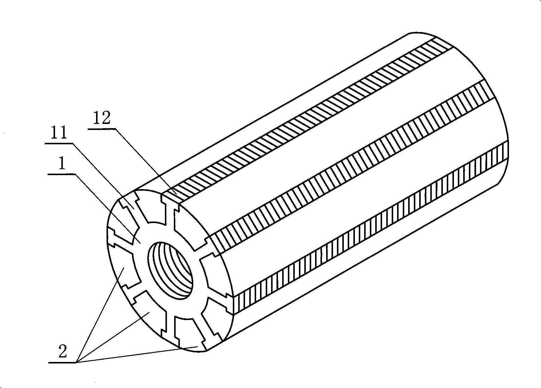
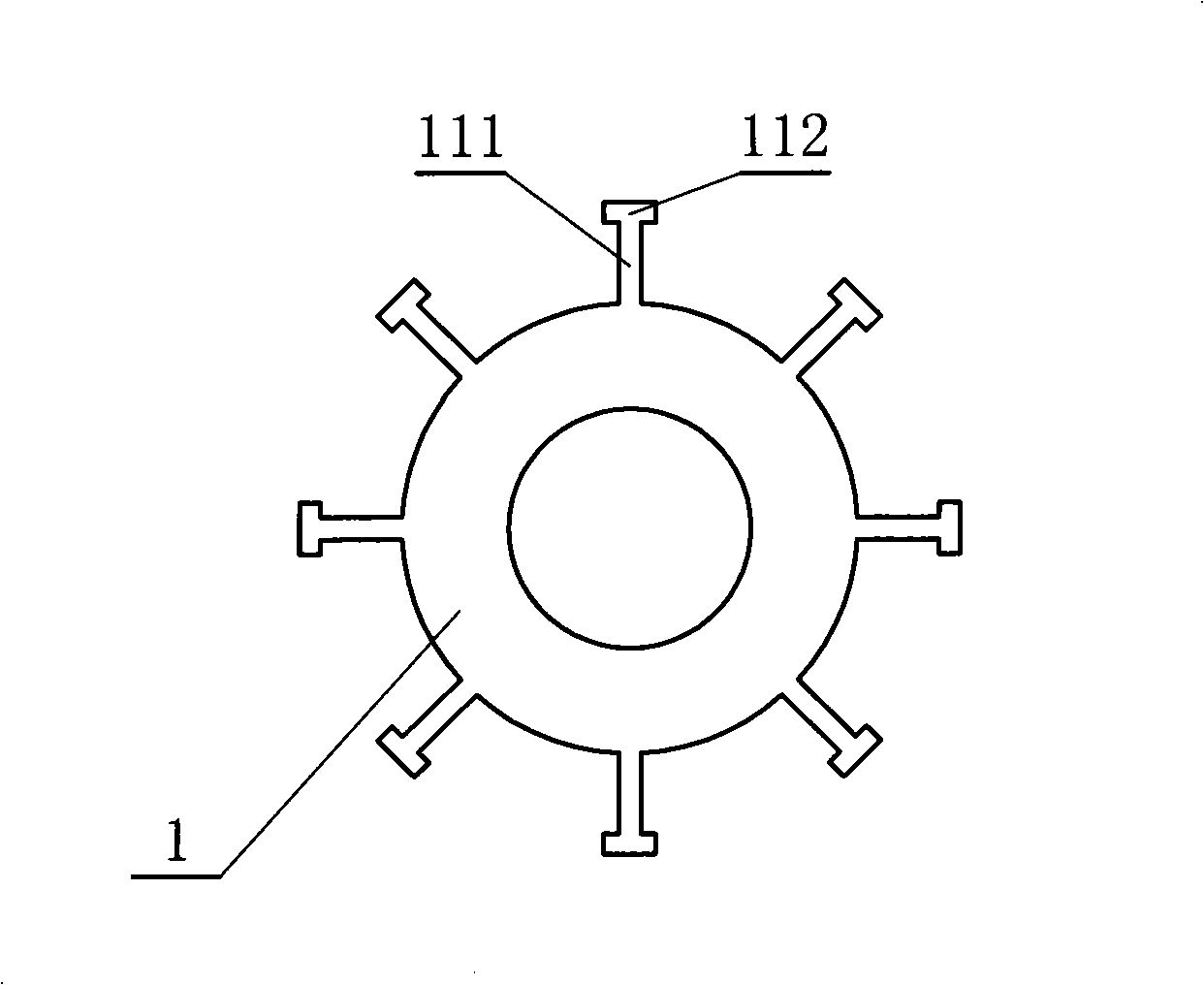
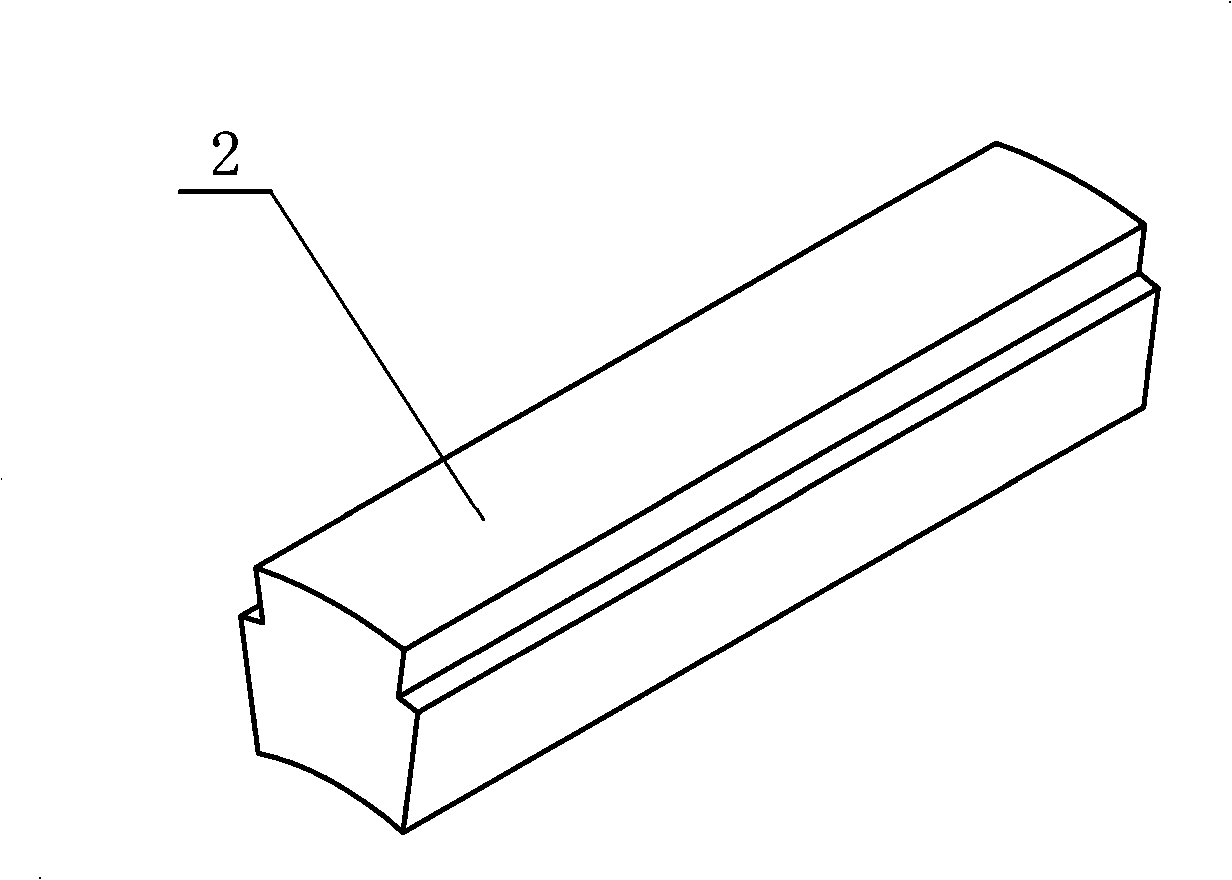
[0020] refer to Figure 1 to Figure 3 It is the first embodiment of a brushless motor rotor of the present invention, a brushless motor rotor, including a rotor core 1 and a magnetic steel 2, and eight motor rotor teeth 11 are arranged in the axial direction of the outer peripheral surface of the rotor core 1 , the motor rotor tooth 11 includes a connecting portion 111 and a limiting portion 112, the connecting portion 111 is rectangular, one end is provided on the outer peripheral surface of the rotor core 1, and the other end is provided with a limiting portion 112, and the limiting portion 112 is also It is rectangular, and the left and right ends are respectively 0.2-1 mm wider than the connection part 111. The rotor core 1 is made of silicon steel sheets or silicon steel sheets 12 with a thickness of 0.2-2 mm; the cross-section of the magnetic steel 2 is Sector shape, the shape of the two side planes is adapted to the shape of the rotor teeth 11 of the motor.

[0021] Wh...

Embodiment 2

[0023] refer to Figure 4 , Figure 5 It is the second embodiment of a brushless motor rotor of the present invention. A brushless motor rotor includes a rotor core 1 and a magnetic steel 2. Eight motor rotor teeth 11 are arranged in the axial direction of the outer peripheral surface of the rotor core 1. The motor rotor teeth 11 have an inverted trapezoidal cross-section, and the shorter end is arranged on the outer peripheral surface of the rotor core 1. The rotor core 1 is formed by superimposing silicon steel sheets or silicon steel sheets 12 with a thickness of 0.2 mm. The cross section of the magnetic steel 2 is fan-shaped, and the shape of the two sides matches the shape of the motor rotor teeth 11 .

[0024] When in use, a magnet 2 is inserted between two adjacent motor rotor teeth 11 of the rotor core 1, the two adjacent magnets 2 are N poles, and the two adjacent magnets are S poles With such an alternate arrangement, eight magnets 2 and several rotor cores 1 form ...


PUM

PropertyMeasurementUnit
Thicknessaaaaaaaaaa
Thicknessaaaaaaaaaa

Abstract

The invention discloses a brushless electric motor rotor, resolving the danger in the prior art that the magnetic blocks are easy to disperse due to the adoption of adhesion type and the integral process of magnet is difficult, deformation often occurs when sintering and the requirement on magnetizing equipment is high due to the adoption of concave-convex coordination. The brushless electric motor rotor comprises a rotor iron core and magnetic steels; over two motor rotor teeth are arranged at the external periphery of the rotor iron core along the axial direction; the width of the top of the motor rotor teeth is larger than the width of the bottom thereof; the transverse section of the magnetic steels is of a fan shape; the shape of the two side planes of the fan-shaped magnetic steels is matched with the shape of the motor rotor teeth; and the number of the magnetic steels is equal to the number of the motor rotor teeth. The invention has the advantages that the brushless electric motor rotor can effectively prevent the magnet from dispersing when the rotor rotates at a high speed, effectively reduce the production cost and improve yield.

Description

technical field [0001] The invention relates to a brushless motor rotor. Background technique [0002] In recent years, the use of brushless motors has become more and more widespread. In the inner rotor type brushless motor which is one of the brushless motors, the magnetic steel is arranged on the outer circumference of the rotor and fixed to the rotor yoke by an adhesive, but as the motor is used, the temperature rises and the The bonding strength is reduced, and there is a danger that the magnetic steel blocks may fly off due to the centrifugal force generated by the rotation of the rotor, and if the number of magnetic poles of the rotor increases, the reliability of preventing the magnetic steel blocks from flying will decrease. [0003] In the patent No. 200510064503.6 brushless motor rotor and brushless motor patent, it is proposed to form an unground concave part in the axial direction of the inner peripheral surface of the magnetic steel, and form a convex part in ...

Claims


Application Information

Patent Timeline
IPC IPC(8): H02K1/27H02K15/02
Inventor 姜卫亮应时立
Owner 姜卫亮
Learn More