
Radiating component and radiating method

A technology for heat-dissipating components and heat-generating components, applied in electrical components, electric solid-state devices, semiconductor devices, etc., can solve problems such as high prices

Inactive Publication Date: 2009-09-09
RAYDIUM SEMICON
View PDF0 Cites 2 Cited by
  • Summary
  • Abstract
  • Description
  • Claims
  • Application Information

AI Technical Summary

Problems solved by technology

Active cooling devices, such as air-cooled cooling fans or circulating cooling systems with coolant and micro-channels, compared with passive cooling devices, active cooling devices have a better cooling effect, but the price More expensive than passive forms of cooling

Method used


Image

  • Radiating component and radiating method
  • Radiating component and radiating method
  • Radiating component and radiating method

Examples


Embodiment Construction

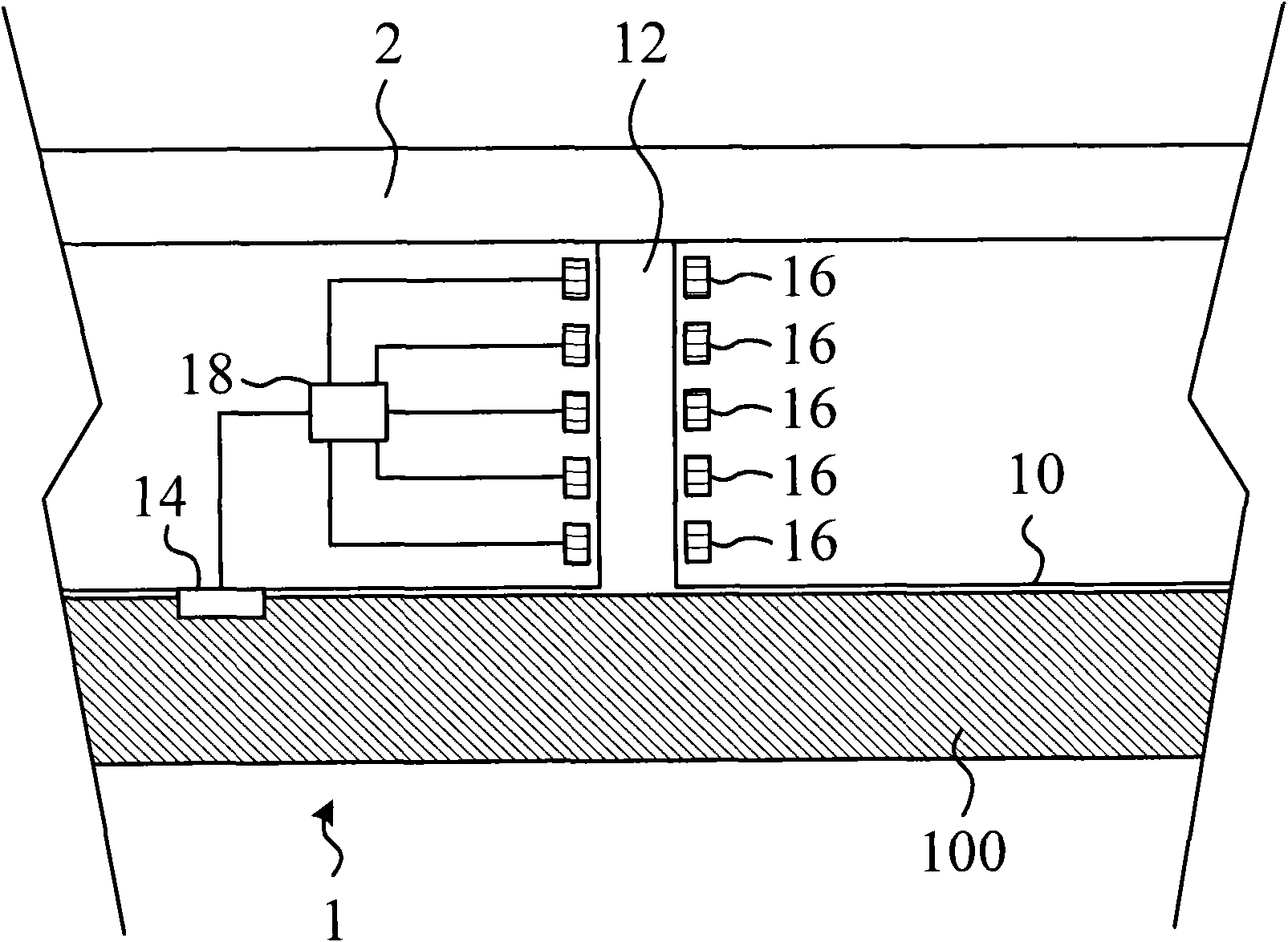
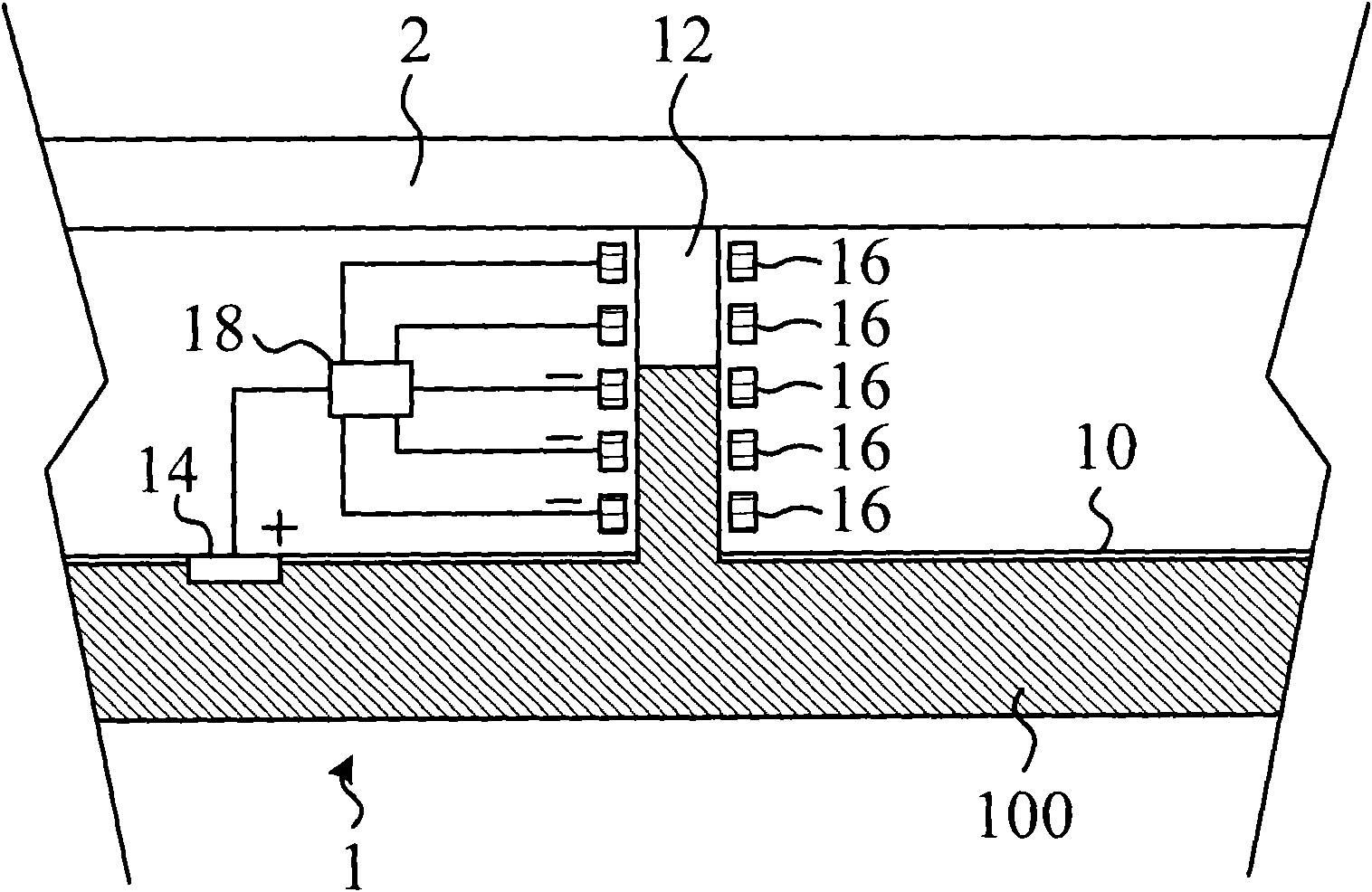
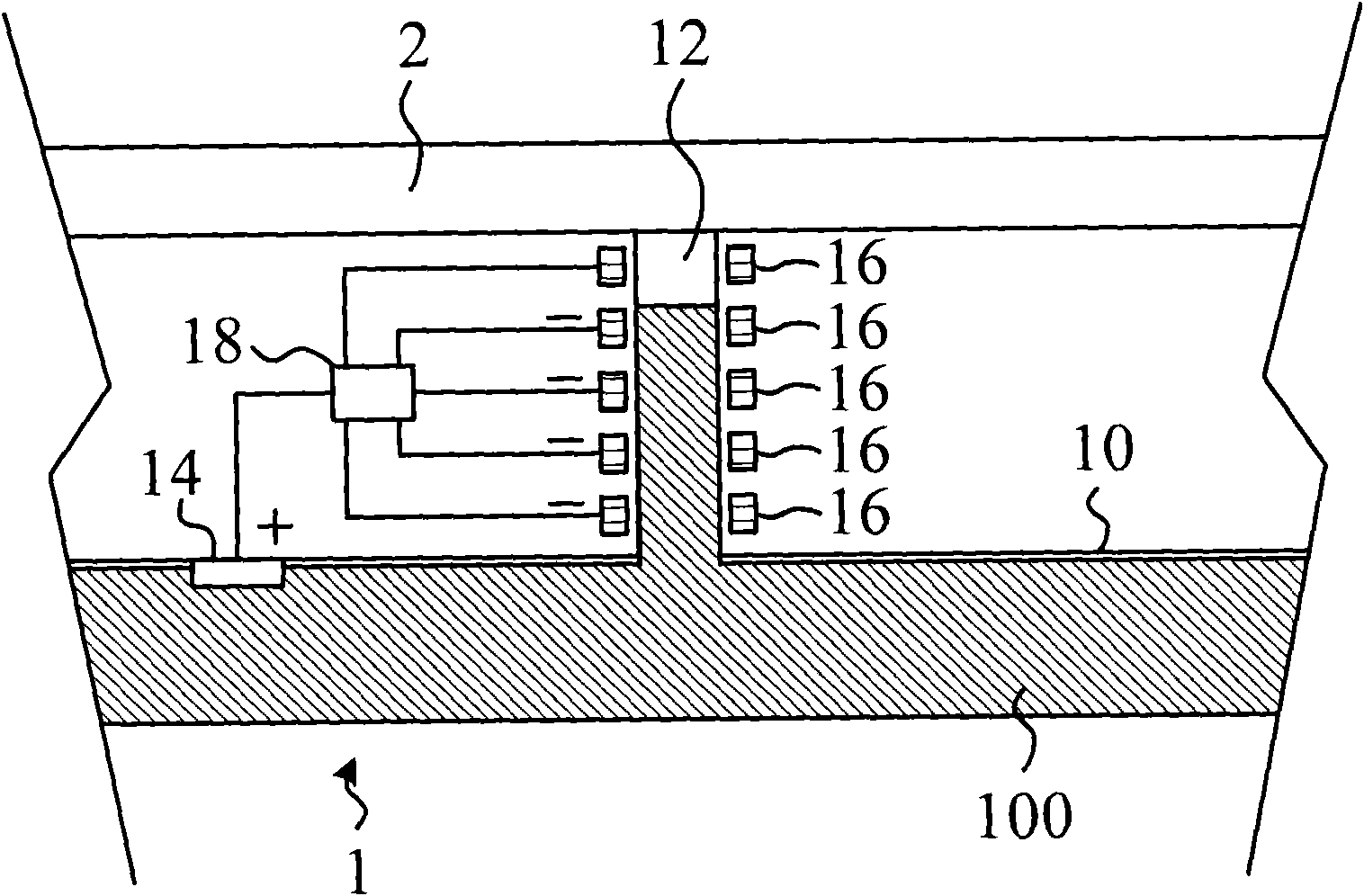
[0041] refer to Figure 1A , Figure 1B as well as Figure 1C , Figure 1A A cross-sectional view of a heat dissipation assembly 1 according to a specific embodiment of the present invention is described; Figure 1B as well as Figure 1C Described Figure 1A A schematic diagram of the first electrode 14 and the second electrode 16 being energized. Such as Figure 1A As shown, the heat dissipation component 1 includes a fluid cavity 10 , a micro-channel 12 , a first electrode 14 and a second electrode 16 . The fluid cavity 10 is used for containing a fluid 100 . The microchannel 12 branches and extends from the fluid chamber 10 , and the other end of the microchannel 12 is close to the heat generating component 2 . Please note that the micro-channel 12 directly contacts the heating component 2 in this specific embodiment, but in practical applications, the heating component (such as a chip) is generally arranged on one side of the circuit board, so the micro-channel can als...


PUM


Abstract

The invention discloses a radiating component, which comprises a fluid cavity, a micro channel, a first electrode and at least one second electrode. The fluid cavity is used for accommodating fluid. The micro channel branches and extends from the fluid cavity to attach to the radiating component. The first electrode is arranged in the fluid cavity and is contacted with the fluid. The second electrodes are arranged on the side wall of the micro channel, and the polarities of the electrodes are opposite to the polarity of the first electrode, wherein the first electrode and the second electrodes are electrified, the first electrode can provide electric charges to the fluid, and the fluid enter the micro channel from the fluid cavity to reach the preset position according to the voltage load degree of the second electrodes so as to approach the radiating component.

Description

technical field [0001] The present invention relates to a heat dissipation component, a heat dissipation system and a heat dissipation method, and in particular, the present invention relates to a heat dissipation component, a heat dissipation system and a heat dissipation method which utilize the electro-humidity effect to regulate the position of cooling liquid. Background technique [0002] In recent years, due to the rapid development of semiconductor technology, the functions of chips have undergone more and more changes, and their sizes have become smaller and smaller. For a single chip, the more changing functions, the more signal transmission pins are needed. On the other hand, the smaller the size, the denser the chip and the signal transmission pins. Under this multi-quantization and high-density design, the heat generated by the chip is much higher than before, and because of the dense structure, the generated heat is less likely to dissipate. Therefore, chip hea...

Claims


Application Information

Patent Timeline
Patent Type & Authority Applications(China)
IPC IPC(8): H05K7/20H01L23/473
Inventor 周忠诚王威李大元
Owner RAYDIUM SEMICON
Learn More