
Radiator with adjustable vertical distance and working method thereof

A heat sink and adjustable technology, applied in energy-saving calculation, cooling/ventilation/heating transformation, climate sustainability, etc., can solve problems such as inability to adjust, and achieve the effect of ensuring normal use, avoiding overheating, and reasonable structure settings

Pending Publication Date: 2022-08-05
TAICANG DOW ELECTRIC
View PDF0 Cites 0 Cited by
  • Summary
  • Abstract
  • Description
  • Claims
  • Application Information

AI Technical Summary

Problems solved by technology

[0004] Purpose of the invention: In order to overcome the above deficiencies, the purpose of the present invention is to provide an adjustable radiator for up and down spacing, which solves the problem that the fins of the central radiator in the traditional technology adopt a fixed structure and cannot be adjusted flexibly according to the specific use

Method used


Image

  • Radiator with adjustable vertical distance and working method thereof
  • Radiator with adjustable vertical distance and working method thereof
  • Radiator with adjustable vertical distance and working method thereof

Examples


Embodiment 1

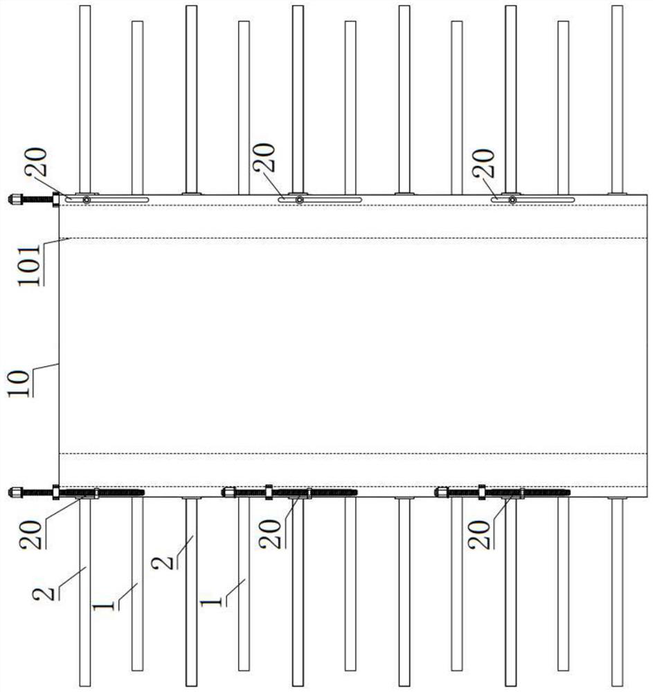
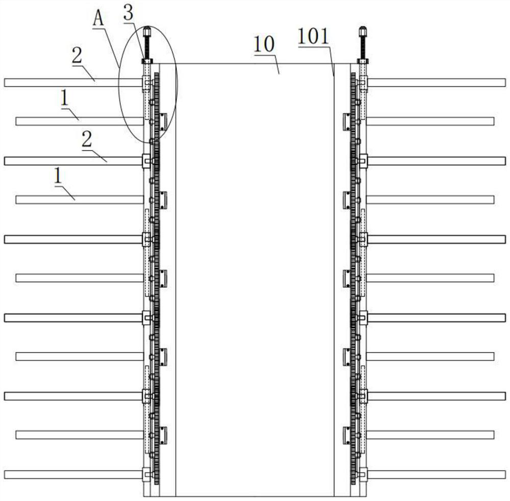
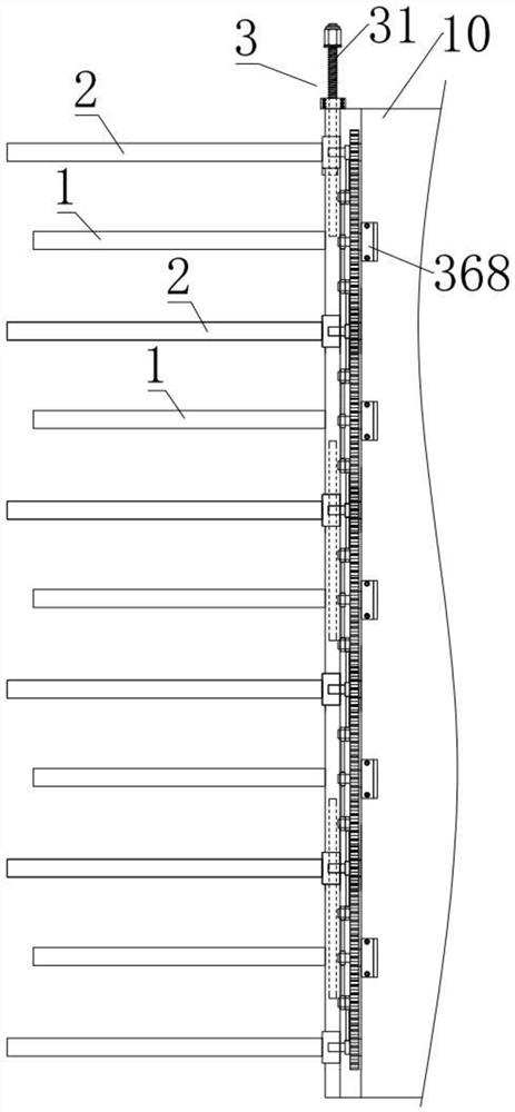
[0034] like figure 1 , 2 The shown radiator with adjustable upper and lower spacing includes a radiator base 10 and two oppositely staggered radiating fin units 20. The radiator base 10 has a rectangular cylindrical structure, and two relatively staggered radiating fins The units 20 are respectively arranged on two opposite outer side walls of the radiator base 10; wherein, the heat dissipation fin units 20 are all composed of a set of heat dissipation fin spacing adjustment modules, and a set of heat dissipation fin spacing adjustment modules along the heat sink The length direction of the base body 10 is arranged in a row. The cooling fin spacing adjustment module includes two fixed cooling fins 1 , two movable cooling fins 2 and a fin spacing adjustment device 3 . The two fixed cooling fins 1 and the two movable cooling fins 2 are spaced apart, and the two fixed cooling fins 1 and the two movable cooling fins 2 are on the same line, the fin spacing adjustment device 3 is a...

Embodiment 2

[0041] like Figure 5 , 6 The shown fin spacing adjustment assembly 36 includes a spacing adjustment driving wheel 361, a fixed rotating wheel 362, a spacing adjustment driving wheel 2 363, a spacing adjustment driving wheel 364, a spacing adjustment slider 365, a rotating rod 366, and a spacing adjustment drive pendulum. Rod 367, gear support seat 368, shaft one 369, shaft two 3610, shaft three 3611 and shaft four 3612, the distance adjustment drive wheel one 361 is connected with the shaft one 369, the active swing rod 34 is away from the end of the driving shaft 33 and one end of the rotating rod 366 are sleeved on the first rotating shaft 369, the middle position of the rotating rod 366 is sleeved on the second rotating shaft 3610, the second rotating shaft 3610 is set on the gear support seat 368, the gear support seat 368 It is arranged in the radiator base 10, the fixed rotating wheel 362 is connected with the second rotating shaft 3610, the other end of the rotating r...


PUM


Abstract

The invention discloses an up-and-down distance adjusting type radiator and a working method, the up-and-down distance adjusting type radiator comprises a radiator base body and two radiating fin units which are oppositely arranged in a staggered mode, and each radiating fin unit is composed of a group of radiating fin distance adjusting modules; the heat dissipation fin spacing adjusting module comprises two fixed heat dissipation fins, two movable heat dissipation fins and a fin spacing adjusting device, the two fixed heat dissipation fins and the two movable heat dissipation fins are arranged at intervals, and the two movable heat dissipation fins are connected with the fin spacing adjusting device; and the fin spacing adjusting device can adjust the positions of the two movable radiating fins. According to the radiator capable of adjusting the distance between the two fixed radiating fins and the two movable radiating fins, the distance between the two fixed radiating fins and the distance between the two movable radiating fins are adjusted through the fin distance adjusting device, so that the contact area between the fins and air is increased, and the good radiating effect of the radiating fins is guaranteed; and the use amount of the radiating fins can be increased or reduced according to real-time conditions, so that a better radiating effect is achieved.

Description

technical field [0001] The invention belongs to the technical field of radiators, and in particular relates to a radiator of an upper and lower spacing adjustment type. The present invention also relates to a working method of the upper and lower spacing adjustment type radiator. Background technique [0002] Most electronic components, such as a central processing unit (CPU), a graphics processing unit (GPU), or a memory, etc., generate heat energy when performing data operations. If the operating electronic components cannot effectively remove the heat energy dissipated by the electronic components, the heat energy accumulated on the electronic components will affect the operation of the electronic components, resulting in a decrease in the operation speed of the electronic components. And when the temperature exceeds the temperature range that the electronic components can withstand, in addition to causing unstable operation of the electronic components, it may also be b...

Claims


Application Information

Patent Timeline
IPC IPC(8): H05K7/20
CPCH05K7/20409H05K7/2039Y02D10/00
Inventor 陶振宇王钱芳
Owner TAICANG DOW ELECTRIC
Learn More