Improved hose

A hose, tubular technology, used in the field of hoses for low temperature applications, can solve problems such as no solution

Active Publication Date: 2009-09-09
BHP PETROLEUM
View PDF11 Cites 6 Cited by
  • Summary
  • Abstract
  • Description
  • Claims
  • Application Information

AI Technical Summary

Problems solved by technology

Although solutions to the problem are generally disclosed in patents such as those mentioned above, there is no commercially viable solution in practice due to the difficulty and cost of riser construction

Method used


Image

  • Improved hose
  • Improved hose
  • Improved hose

Examples


Embodiment Construction

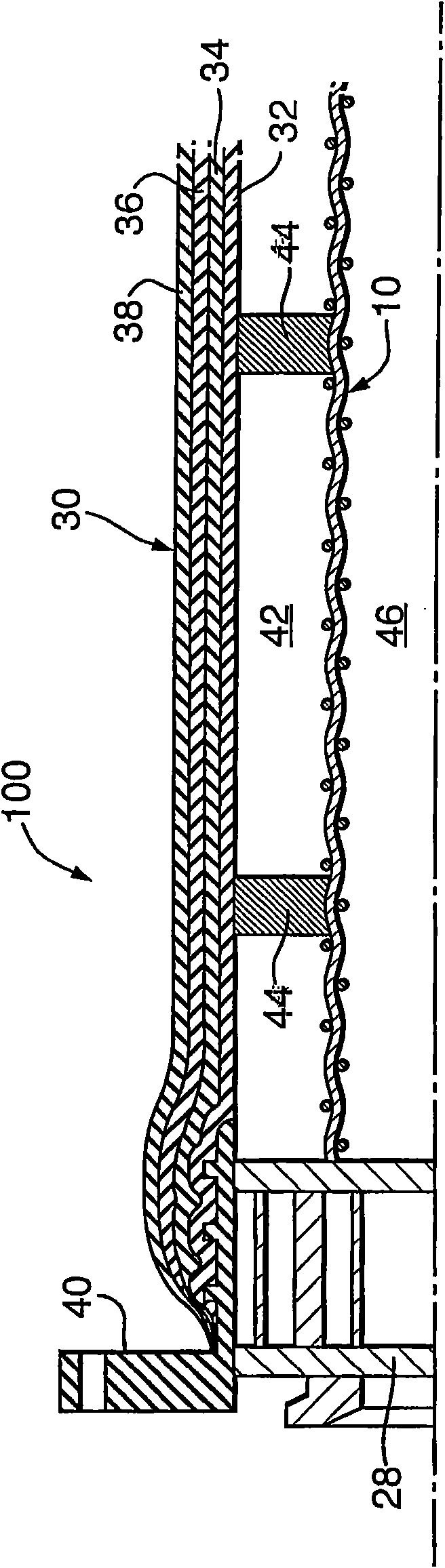
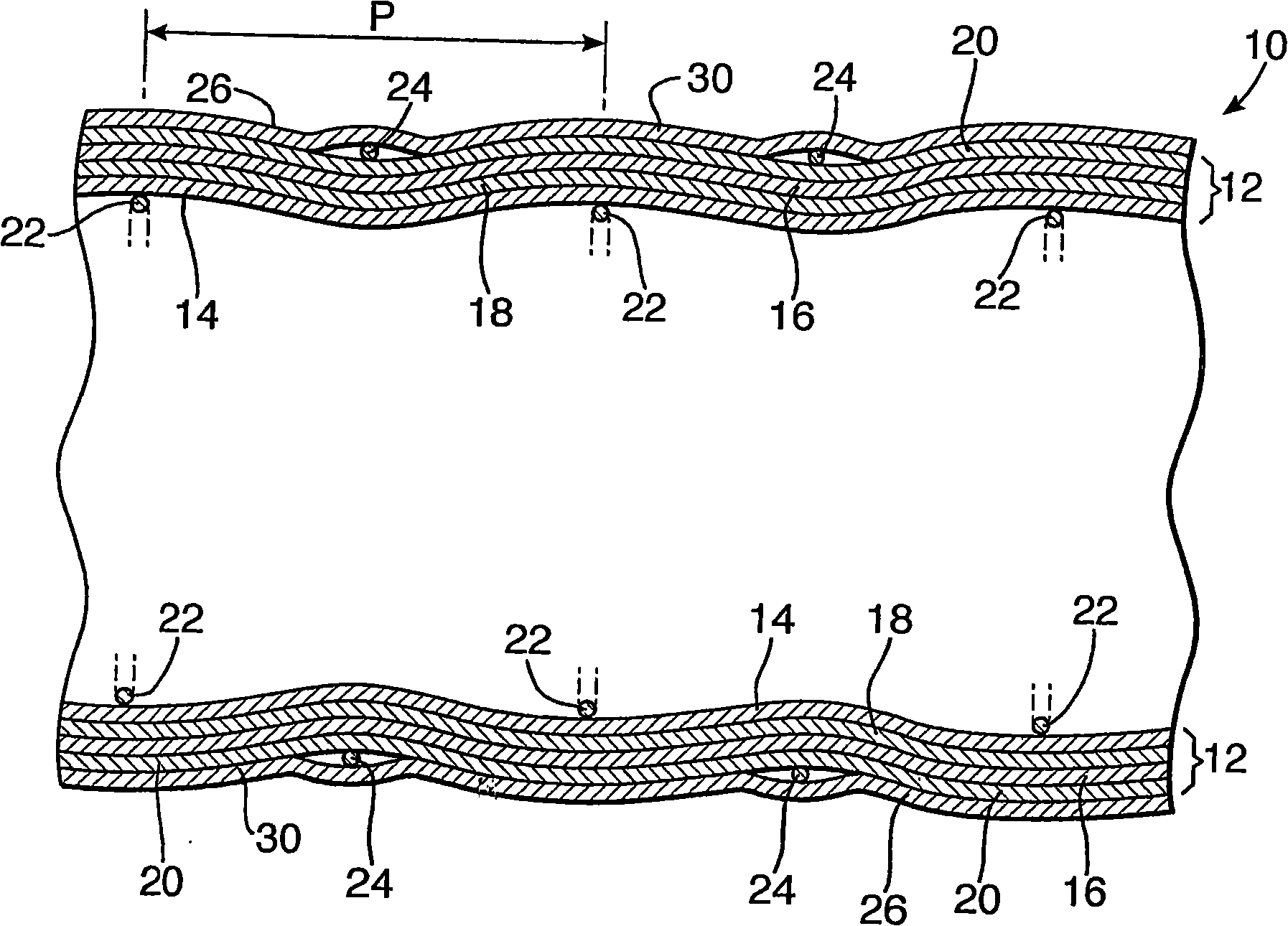
[0131] see first figure 1 and 2 , a hose according to the invention is indicated generally at 100 . The hose comprises an inner tubular structure 10 and an outer tube 30 .

[0132] The inner tubular structure 10 comprises a tubular body 12 comprising an inner reinforcement layer 14 , an outer reinforcement layer 16 , and a sealing layer 18 sandwiched between layers 14 and 16 . A generally tubular sheath 20 in the form of webbing for providing axial reinforcement is arranged around the outer surface of the outer reinforcement layer 16 .

[0133] The tubular body 12 and the tubular sheath 20 are located between clamping members in the form of an inner helical coil wire 22 and an outer helical coil wire 24 . The inner and outer wires 22 and 24 are arranged such that they are offset from each other by a distance corresponding to half the pitch length of the coil.

[0134] An insulating layer 26 is disposed around the outer wire 24 . The insulating layer 26 may be, for example...


PUM


Abstract

A hose (100) comprises an inner tubular structure (10), an outer tube (30) and an insulation layer, wherein the inner tubular structure (10) comprises a tubular body disposed between inner and outer gripping members, the tubular body including a sealing layer, and being formed of a material capable of withstanding cryogenic temperatures, wherein the outer tube (30) comprises a rubber layer (32) and a reinforcing layer (34, 36) disposed around the rubber layer (32), wherein the insulation layer is either incorporated in the inner tubular structure and / or is disposed between the inner tubular structure and the outer tube.

Description

technical field [0001] The present invention relates to a hose, in particular to a hose suitable for cryogenic applications. Background technique [0002] There are many systems for transporting fluids between offshore structures, such as ships or other platforms, and subsea pipelines. Examples of such systems include: [0003] (1) Traditional multi-buoy mooring (CMBM) system. In this system, a riser runs directly down the pipeline from the offshore connection, with support buoys placed occasionally along the length of the hose. [0004] (2) Single tower mono-mooring (STM) system. In this system, a mooring tower is fixed to the seabed and extends to sea level. Mooring towers support pipelines that run from sea level to offshore structures. A hose or other pipe may extend from the offshore structure and be connected to the end of the hose at the top of the mooring tower. [0005] (3) Single anchor-leg mooring (SALM) system. In this system, a buoy is positioned adjacent...

Claims


Application Information

Patent Timeline
Patent Type & Authority Applications(China)
IPC IPC(8): F16L59/14
CPCF16L59/141F16L59/153F16L11/118F16L11/121F16L11/112
Inventor J·A·维茨D·C·考克斯
Owner BHP PETROLEUM
Why Eureka
Try Eureka