Self-propelled corn harvester

A harvester and self-propelled technology, which is applied in the direction of harvesters, cutters, crop processors, etc., can solve the problems of high power consumption, affecting farming, and easy failures, etc., to achieve low power consumption, not easy to break down, easily damaged effects

Inactive Publication Date: 2009-09-16
程辉 +1
View PDF0 Cites 25 Cited by
  • Summary
  • Abstract
  • Description
  • Claims
  • Application Information

AI Technical Summary

Problems solved by technology

[0003] 1. The cross-sections of the chute and the sliding rod of the shifting rod are a matching rectangle. When the sliding rod slides in the chute, the chute does not constrain the sliding rod firmly, and the sliding rod is prone to radial runout, causing the fixed blade and the moving blade to The distance between them is increased, and it is easy to clamp debris, which will affect the cutting operation and cause damage to the blade;
[0004] 2. The shaft seat of the ear picking roller is directly installed on the frame. When the ear picking roller is working, the shaft of the ear picking roller is subjected to radial force, and the radial force acts on the input shaft, which affects the concentricity between the input shaft and the ear picking roller shaft. In the harvesting operation, the bearing load of the input shaft of the picking roller is relatively large, and it is easy to be damaged;
[0005] 3. The crushing effect of the straw crusher is poor, and the large straw fragments will affect the cultivation after returning to the field;
[0006] 4. The corn cob conveyor has a frame, and there is a steel groove on the frame. There are driving rollers and driven rollers at both ends of the groove, and there are steel scrapers in the groove and between the driving roller and the driven roller. , the power consumption is large when lifting and conveying the ear of corn, and it is easy to break down

Method used


Image

  • Self-propelled corn harvester
  • Self-propelled corn harvester
  • Self-propelled corn harvester

Examples


Embodiment Construction

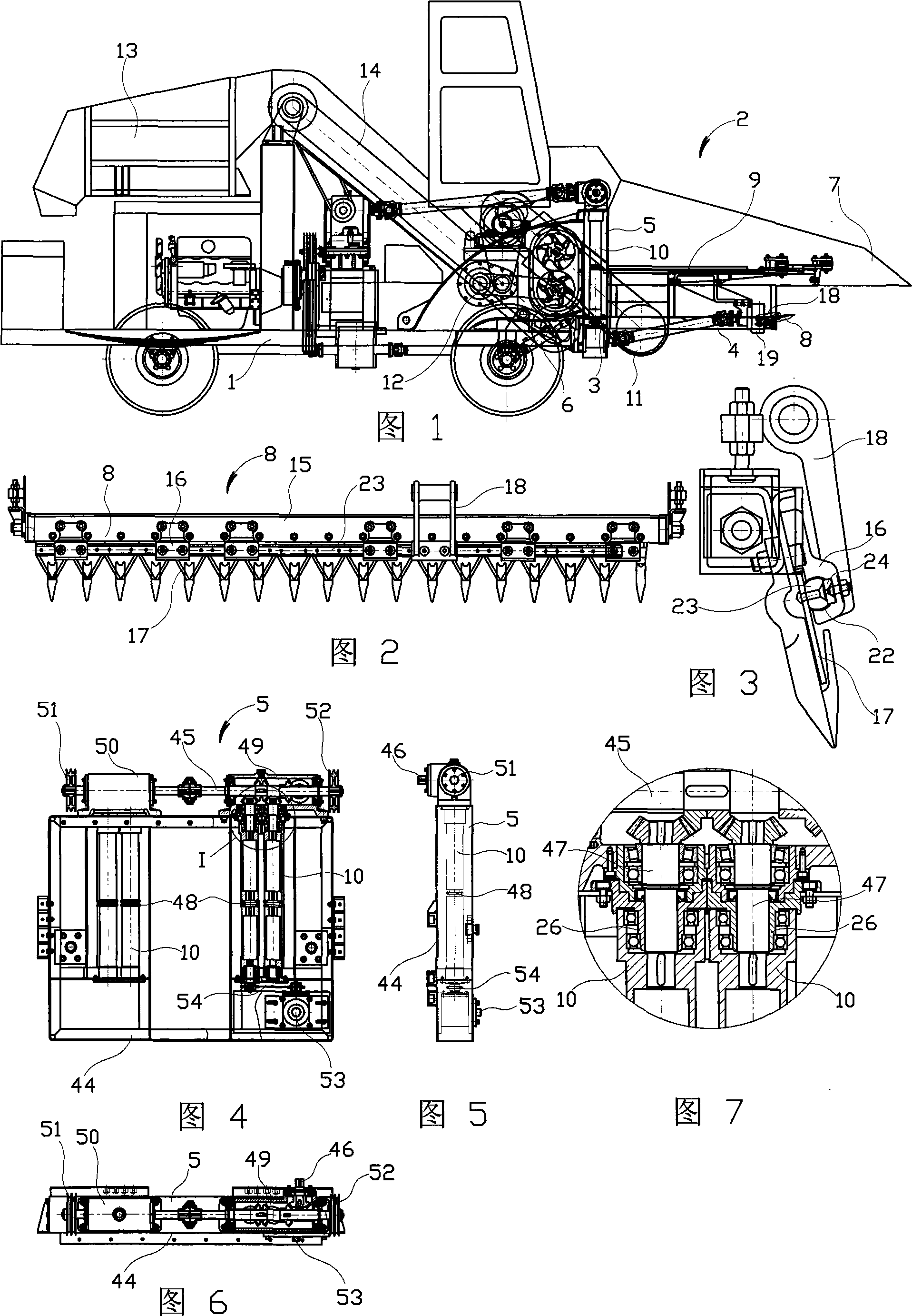
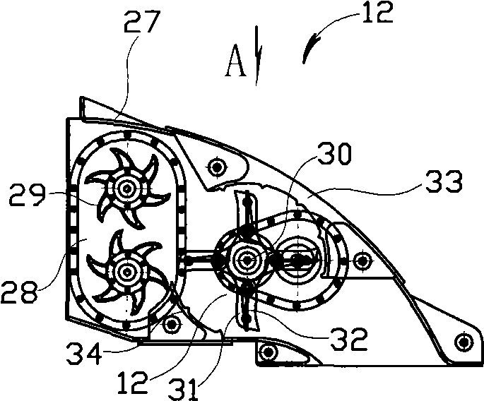
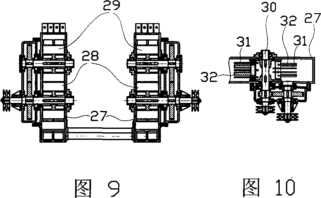
[0033] Figure 1~ Figure 16 Among them, the self-propelled corn harvester has a motor vehicle 1, the front part of the motor vehicle frame is hinged with a header 2, the header has an L-shaped frame 3, the L-shaped frame has a horizontal frame 4 and a vertical frame 5, and the vertical frame of the header There is a hydraulic cylinder 6 between the frame and the horizontal frame of the header. There is a grain lifter 7 at the front end of the horizontal frame of the header. There is a cutting knife 8 under the grain lifter. There is a clamping conveyor chain 9 behind the cutter. The rear of the clamping conveyor chain, vertical Vertical ear picking roller 10 is arranged on the frame, corn ear groove 11 is arranged on the front and bottom of picking ear roller, straw pulverizer 12 is connected with the rear of picking ear roller, ear box 13 is arranged at the rear of the vehicle frame, and peeler is arranged on the ear box top (not shown in the figure), there is corn ear convey...


PUM


Abstract

The invention relates to a self-propelled corn harvester. A cutting platform is hinged at the front part of an automotive vehicle frame and is provided with a grain lifter, a cutting knife, a gripping conveyor chain, a snapping roll and a stalk crusher, wherein the middle part of the frame is provided with a corn ear conveyor, while and the rear part is provided with a fruit ear box, the cross sections of a chute below pressing plates evenly distributed on a cross beam of the cutting knife and a sliding rod in the chute are mutually matched drum shapes, an anti-attrition lining plate is arranged between the pressing plates and the sliding rod, the snapping roll is arranged on the frame through an unloading sleeve, a crankshaft in a shell of the straw grinder is hinged with hammer leaves, a radial material-throwing plate is arranged between the hammer leaves on the crankshaft, the inner wall of the shell is provided with an upper screw plate and a lower screw plate, and a full rubber corrugated flange conveying belt is arranged between a driving roller and a driven roller of the core ear conveyor. The sliding rod of the cutting knife is not easy to beat and is advantageous for cutting operations, and the bearing load of an input bearing of the snapping roll is small so that the snapping roll is not easy to be damaged; corn stalk grains after crushing are small and does not influence farming after being applied to fields; and the full rubber corrugated flange conveying belt conveys corn ears with small power consumption in the process of conveying the core ears, and is not easy to go wrong.

Description

technical field [0001] The invention relates to a self-propelled corn harvester, in particular to a cutter, an ear picking roller, a straw grinder and a corn ear conveyor of the self-propelled corn harvester. Background technique [0002] The self-propelled corn harvester has a motor vehicle, the front of the motor vehicle frame is hinged with a header, the header has an L-shaped frame, the L-shaped frame has a horizontal frame and a vertical frame, and the vertical frame of the header is connected to the frame. Hydraulic cylinder, the front end of the horizontal frame has a grain lifter, there is a cutting knife under the grain lifter, there is a clamping conveyor chain behind the cutter, behind the clamping conveyor chain, there is an ear picking roller on the vertical frame, and the front and bottom of the ear picking roller There is a corn ear trough, a straw grinder behind the ear picking roller, an ear box at the rear of the frame, a peeling machine above the ear box, ...

Claims


Application Information

Patent Timeline
Patent Type & Authority Applications(China)
IPC IPC(8): A01D45/02A01D43/10A01D69/06A01D34/13A01D82/00
Inventor 程辉崔建国
Owner 程辉
Why Eureka
Try Eureka