Floor with internal heat-conducting structure

A heat-conducting, flooring technology, applied in the field of flooring, can solve the problems of not saving space, high heat loss rate, and large floor thickness

Inactive Publication Date: 2010-12-29
上海溢邦装饰建材有限公司
View PDF1 Cites 3 Cited by
  • Summary
  • Abstract
  • Description
  • Claims
  • Application Information

AI Technical Summary

Problems solved by technology

1. The heat conduction of the floor relies on the geothermal layer on the ground, so the heat loss rate is still high; 2. The floor is thick and does not save space

Method used


Image

  • Floor with internal heat-conducting structure
  • Floor with internal heat-conducting structure
  • Floor with internal heat-conducting structure

Examples


Embodiment Construction

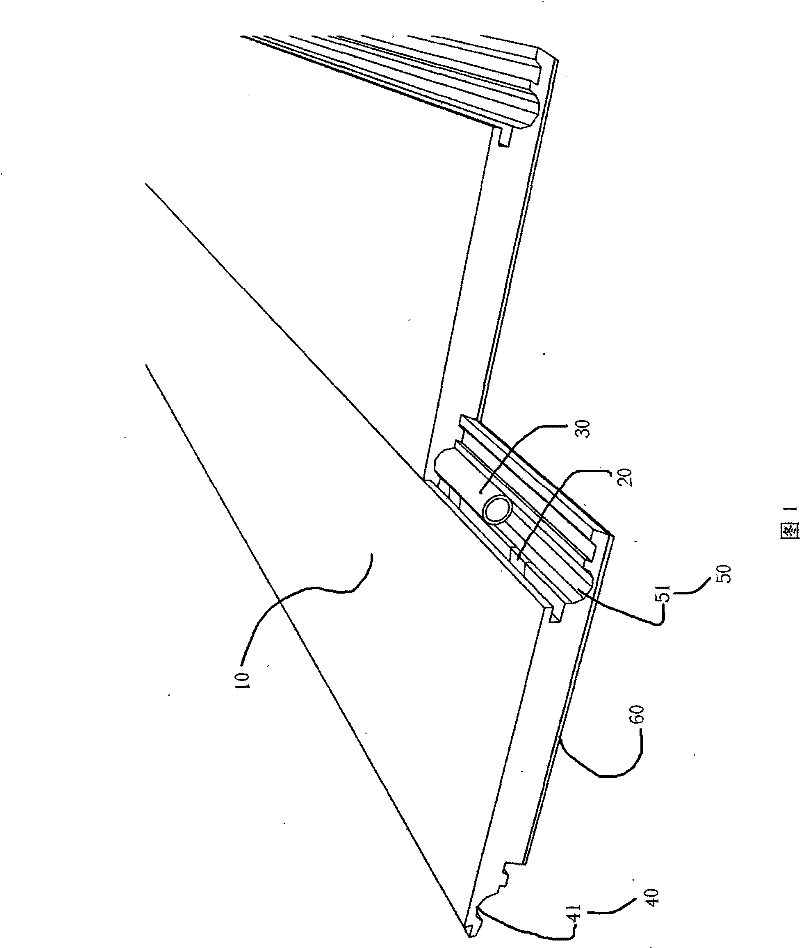
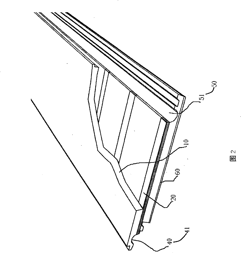
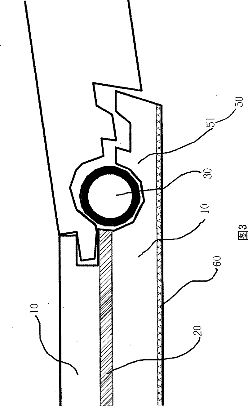
[0022] As shown in Figures 1 to 3, a preferred embodiment of a floor with an internal heat conduction structure is illustrated. The floor includes a floor body 10 , a plurality of heat-conducting medium objects 20 , a floor heating pipe 30 , an upper locking member 40 and a lower locking member 50 .

[0023] Each of the heat-conducting medium objects 20 is located laterally inside the floor body 10, and one end of each of the heat-conducting medium objects 20 is in contact with the floor heating pipe 30, so that the heat in the floor heating pipe 30 is directly Conduction and rapid distribution to various positions of the floor, avoiding the loss of the heat.

[0024] The upper locking member 40 is located on one side of the floor body 10, defining an upwardly convex upper support chamber 41, and the lower locking member 50 is located on the other side of the floor body 10, defining a A concave lower support cavity 51, wherein the floor heating pipe 30 is horizontally placed ...


PUM


Abstract

The invention relates to a floor with an internal heat-conducting structure, comprising a floor body, a plurality of heat-conducting media, a ground-heating pipe, an upper locking fastener and a lower locking fastener. Each heat-conducting medium is horizontally positioned in the floor body and one end thereof is contacted with the ground-heating pipe. The upper locking fastener is positioned at one side of the floor body and defines an upper support cavity which is convex upward; the lower locking fastener is positioned at the other side of the floor body and defines a lower support cavity which is concave downward; wherein the ground-heating pipe is horizontally arranged in the lower support cavity. When the upper locking fastener of the floor is meshed with the lower locking fastener of the adjacent floor, the upper support cavity and the lower support cavity are matched to form a containing cavity; and the ground-heating pipe is contained in the containing cavity, therefore, the ground-heating pipe is embedded into two adjacent floors, not only the thickness of the paved floor is reduced, but also heat is directly transmitted to each heat-conducting medium from the ground-heating pipe, thus reducing the heat loss.

Description

technical field [0001] The invention relates to a floor, in particular to a floor with an internal heat conduction structure. Background technique [0002] With the development of science and technology, the traditional heating technology has undergone changes, and floor heating has become a popular trend, so floor heating has emerged as the times require. At present, solid wood composite flooring and laminate flooring mainly rely on the conduction and heat dissipation of the wood body. Due to the low thermal conductivity of wood and the slow heat conduction speed, the heat consumption of floor heating is very high. That is to say, these floors are only suitable for floor heating by their own materials. The true sense of the dedicated floor heating. In addition, these underfloor heating floors are mainly laid on the underfloor heating floor. The disadvantage is that the cement layer on the ground needs to be heated first, and then transmitted to the floor on the ground. He...

Claims


Application Information

Patent Timeline
Patent Type & Authority Patents(China)
IPC IPC(8): E04F15/02F24D3/16
Inventor 郭兆军
Owner 上海溢邦装饰建材有限公司
Why Eureka
Try Eureka