
Method for operating a water circulation system
- Summary
- Abstract
- Description
- Claims
- Application Information
AI Technical Summary
Benefits of technology
Problems solved by technology
Method used
Image

Examples
Embodiment Construction
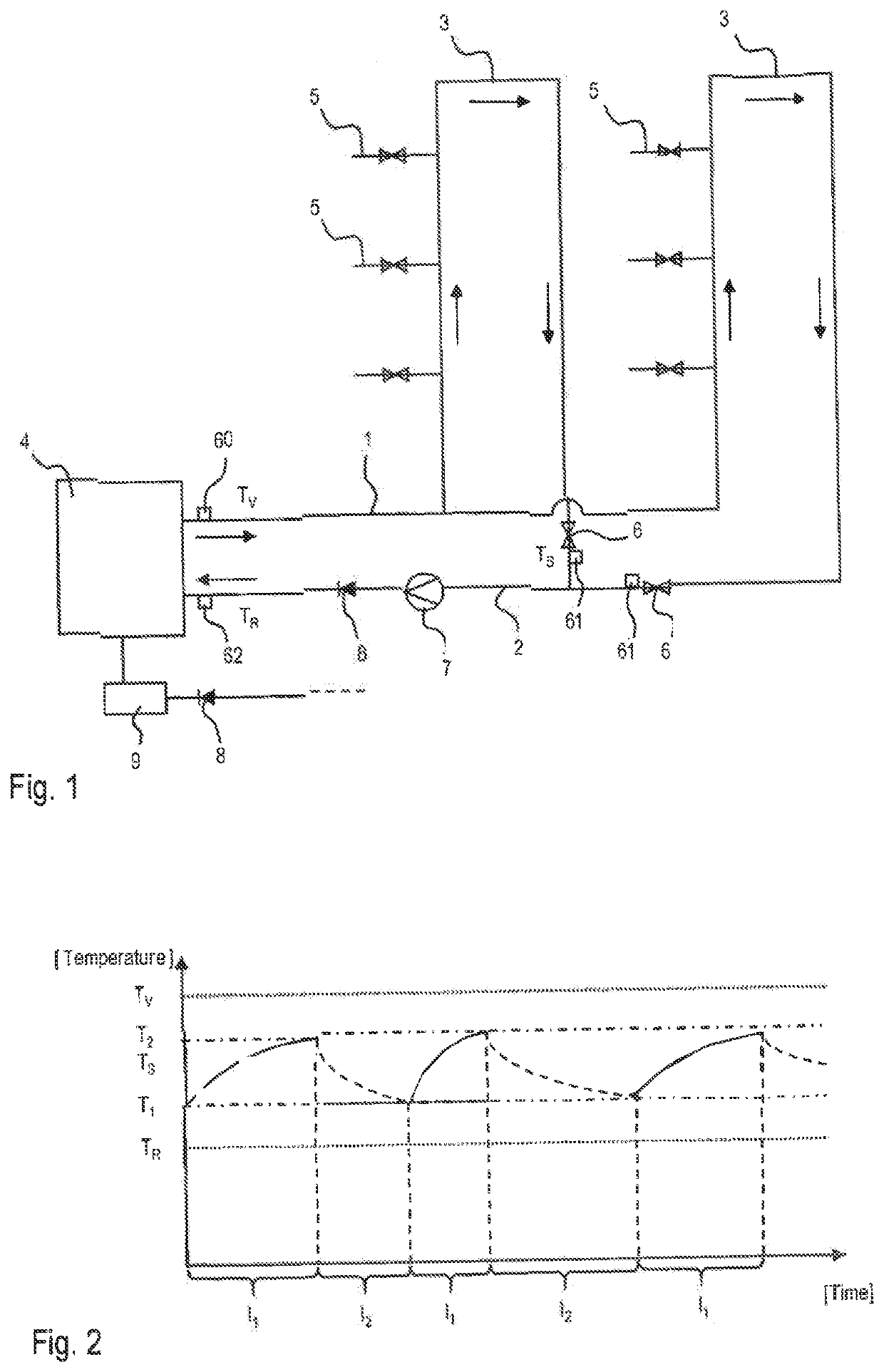
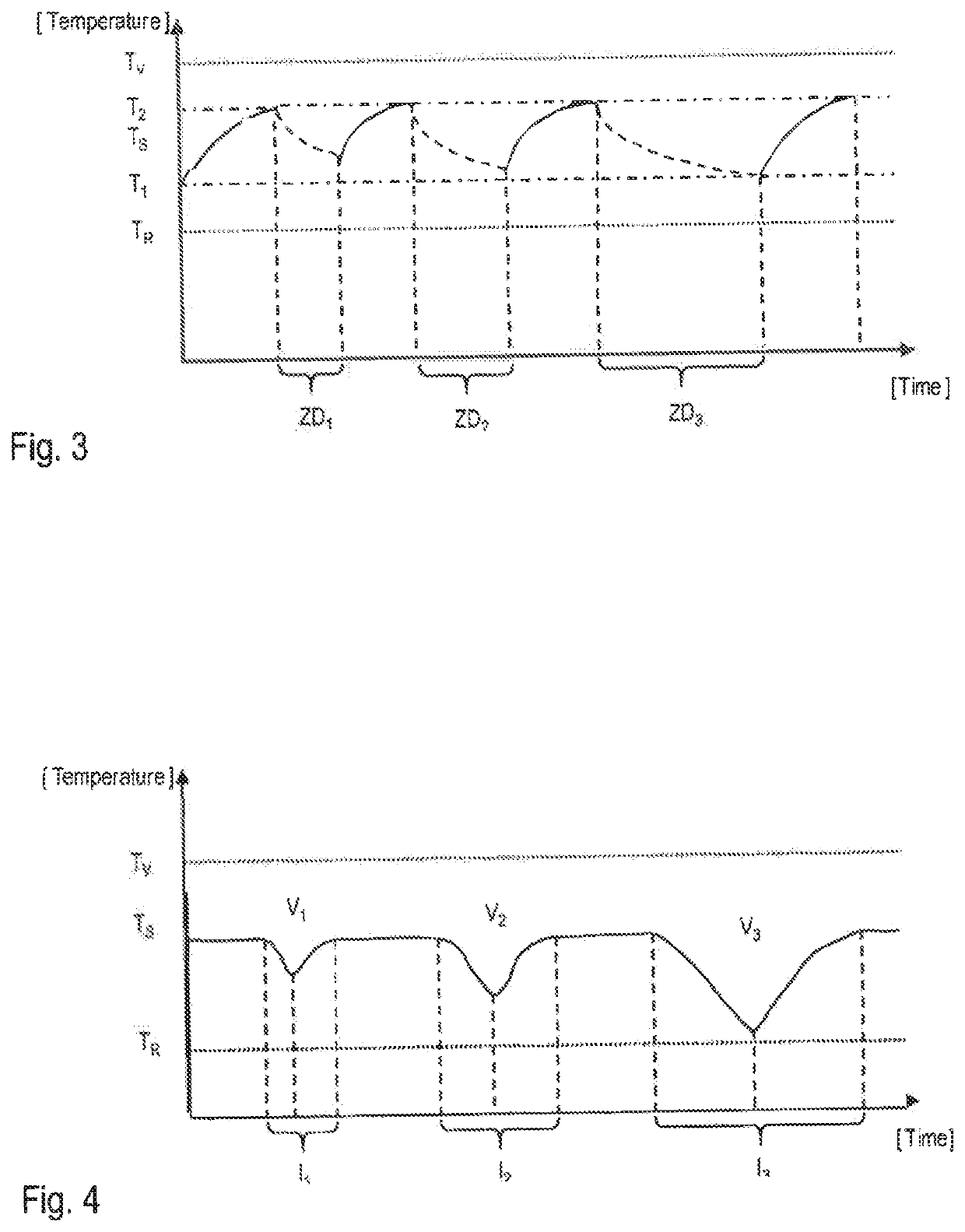
[0068]FIG. 1 shows a schematic representation of a water circulation system for carrying out the method according to the invention. The system comprises a supply line 1, a return line 2, two strand 3 which connect the supply line 1 to the return line 2. The system further comprises a temperature control unit 4, which connects the supply line 1 with the return line 2, whereby in one flow direction, water can circulate from the supply line 1, via the two strands 3, the return line 2 and the temperature control unit 4 back to the supply line 1. The system further comprises several consumers 5, which are arranged along the strand 3 and with which water can be drawn from the circulation system. In each strand 3, a valve 6 is provided, which is arranged in the region of the strand 3 which opens into the return line 2. I.e. the valve 6 is arranged in the region of the end of the strand 3. With each valve 6, the flow rate of the water in the respective strand can be changed. In the supply l...
PUM
 Abstract
Description
Claims
Application Information