Automatic push steel into furnace control system and method for push steel walking heating furnace

A control method and control system technology, which is applied in the field of automatic steel pushing into the furnace control system, can solve problems affecting furnace pressure control, cold air inhalation, thermal efficiency loss, etc., and achieve the goals of reducing thermal efficiency loss, good furnace pressure, and good control Effect

Active Publication Date: 2021-07-27
新余钢铁股份有限公司
View PDF4 Cites 0 Cited by
  • Summary
  • Abstract
  • Description
  • Claims
  • Application Information

AI Technical Summary

Problems solved by technology

[0002] The steel loading design of the walking heating furnace is generally two types: end steel feeding into the furnace and pushing steel into the furnace. A section of transition bench synchronized with the stepping mechanism is designed at the furnace feeding end of the push steel walking furnace. The transition bench is located between the roller table and the furnace. Between the walls, that is, outside the furnace, the fixed beams and movable beams in the furnace are extended by the stepping mechanism installed on the transition platform, but it is not a water beam design, but a set of steel structure frames; when working, the billet is pushed by the steel pusher The upper transitional platform relies on the movable part of the transitional platform and the fixed cooperation to transport the billet to the furnace according to the running track of the stepping mechanism "up-forward-down-back". The stepping mechanism of the transitional platform and the walking beam is segmented Due to the transitional platform running with the stepping mechanism during production, the feed furnace door cannot fall and is in a normally open state, resulting in loss of thermal efficiency, affecting energy saving and thermal efficiency, and easily causing cold air to be sucked in, affecting the furnace. pressure control

Method used


Image

  • Automatic push steel into furnace control system and method for push steel walking heating furnace
  • Automatic push steel into furnace control system and method for push steel walking heating furnace

Examples


Embodiment Construction

[0025] The specific implementation of the present invention will be described in further detail below by describing the embodiments with reference to the accompanying drawings, so as to help those skilled in the art have a more complete, accurate and in-depth understanding of the inventive concepts and technical solutions of the present invention.

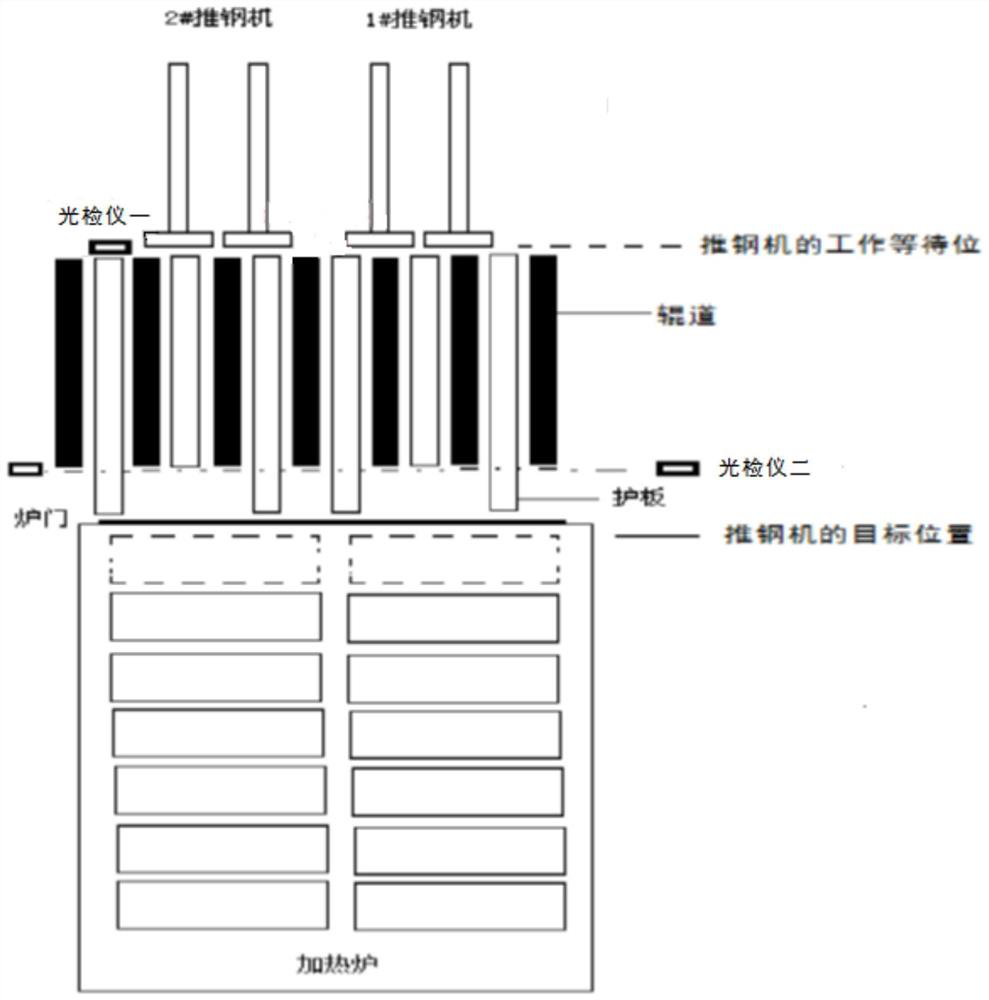
[0026] figure 1 The schematic diagram of the automatic steel-pushing-in furnace control structure of the pusher-type walking heating furnace provided for the embodiment of the present invention, for the convenience of description, only shows the parts related to the embodiment of the present invention.

[0027] The system includes:

[0028] The steel pusher is located on the opposite side of the furnace door at the feed end of the heating furnace, and is set on the side of the transmission motor of the conveyor roller table. It is the zero position of the steel pusher stroke, and the billet is on the conveying roller table at the ...


PUM


Abstract

The invention discloses a control system and method for automatically pushing steel into the furnace of a pushing steel-type walking heating furnace. The method is as follows: after the billet is centered at the billet waiting position, wait for the steel to be pushed; if the walking beam is in the lower position, and When the vacancy in the furnace satisfies the steel pushing distance, a furnace door opening prompt is issued; the furnace door is opened to a high position based on the furnace door opening finger, and a steel pushing prompt is issued based on the position signal of the furnace door opening; the steel pushing machine in the working waiting position is based on the steel pushing command Push the billet forward, and push the billet on the conveying roller table to the fixed beam in the furnace; after the pusher reaches the target position, send a reset command to the pusher, and the pusher returns to the working waiting position; After reaching the working waiting position, a furnace door closing prompt is issued, and the furnace door performs a closing action based on the furnace door closing command until the furnace door is completely closed. The furnace door is only open when the steel is pushed into the furnace, and it is closed at other times, which greatly reduces the heat loss.

Description

technical field [0001] The invention belongs to the technical field of walking heating furnaces, and more specifically, the invention relates to a control system and method for automatically pushing steel into the furnace of a pushing steel walking heating furnace. Background technique [0002] The steel loading design of the walking heating furnace is generally two types: end steel feeding into the furnace and pushing steel into the furnace. A section of transition bench synchronized with the stepping mechanism is designed at the furnace feeding end of the push steel walking furnace. The transition bench is located between the roller table and the furnace. Between the walls, that is, outside the furnace, the fixed beams and movable beams in the furnace are extended by the stepping mechanism installed on the transition platform, but it is not a water beam design, but a set of steel structure frames; when working, the billet is pushed by the steel pusher The upper transitiona...

Claims


Application Information

Patent Timeline
Patent Type & Authority Patents(China)
IPC IPC(8): F27B9/40F27B9/24
CPCF27B9/2407F27B9/40
Inventor 刘永龙周萍肖颖谢爱平周焱民唐法丁李玉清束家彪赵房亮
Owner 新余钢铁股份有限公司
Why Eureka
Try Eureka