Integrally adjustable automatic water elevator unit

A water lifter and unit technology, applied in the direction of engine components, machines/engines, mechanical equipment, etc., can solve the problems of being limited, reducing energy consumption, and not being easy to install, so as to reduce the effect of gravity, reduce mechanical losses, and facilitate water Available effects

Inactive Publication Date: 2013-05-22
吕忠旺
View PDF2 Cites 0 Cited by
  • Summary
  • Abstract
  • Description
  • Claims
  • Application Information

AI Technical Summary

Problems solved by technology

[0002] In the current social production, agricultural irrigation, water conservancy equipment, and South-to-North Water Diversion projects, among the mechanical equipment that uses water flow to drive its own machine to lift water, the water energy utilization power of the water lifter is not very high, and the installation and use are not easy enough. Relatively large, it is inconvenient to adjust the amount of water to be lifted, and the lift of the water is not very high, so that the water lifting work cannot be effectively developed and utilized in a large area
[0003] The Chinese patent application with the application number 200510063101.4 discloses a technical solution of "water energy conversion automatic water lifting machine, unit, and machine group". There are many infrastructure requirements, and the installation is not easy enough. The mechanism of the water lifter uses a double-chain water lift chain to hang the water cylinder, which cannot reduce its own weight and energy consumption. The adjustment of the water lifting volume depends on replacing the water cylinder, which is not convenient enough. If the water lifting head is higher, there is nothing to do, so the water lifting work is limited
The Chinese patent application 200510074833.3 I applied for also discloses an "adjustable double-blade bucket transmission chain turbine", although it has a good effect on the overall utilization of water energy, but no effective utilization measures have been proposed in terms of water lifting

Method used


Image

  • Integrally adjustable automatic water elevator unit
  • Integrally adjustable automatic water elevator unit
  • Integrally adjustable automatic water elevator unit

Examples


Embodiment 1

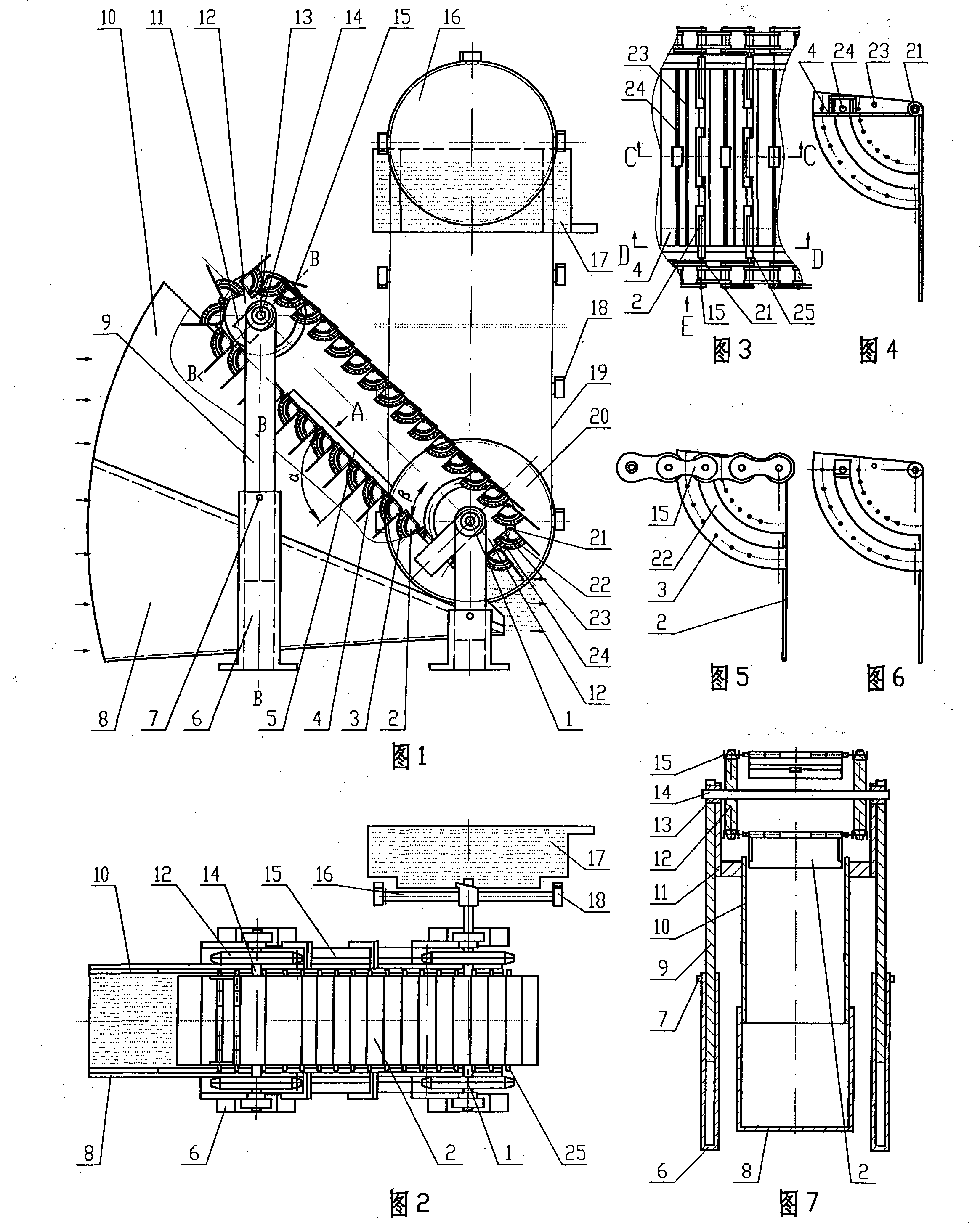
[0040] Such as figure 1 , figure 2 , image 3 , Figure 4 , Figure 5 , Figure 6 , Figure 7 , Figure 10 , Figure 11 , Figure 12 , Figure 13 As shown, the present invention includes a water machine and a water lifter driven coaxially by the water machine, the driving sprocket shaft 1 and the driven sprocket shaft 14 of the water machine are installed on the lifting legs 9, and the chain belt plate 4 is coaxial The suit is equipped with an adjustable movable leaf bucket-shaped hydraulic plate 2, and the water energy machine also includes a U-shaped bottom groove 8 and baffles 10 on both sides, which form a pressure-type cone volume chamber with the chain belt plate 4; the water lifter is a single chain Type water lifter, the water lift sprocket 20 is installed on the driving sprocket shaft 1 of the water energy machine, and the closed single chain around the water lift sprocket 20 and the unloading sprocket 16 is hung with a movable leaf plastic cover 31 and The...

Embodiment 2

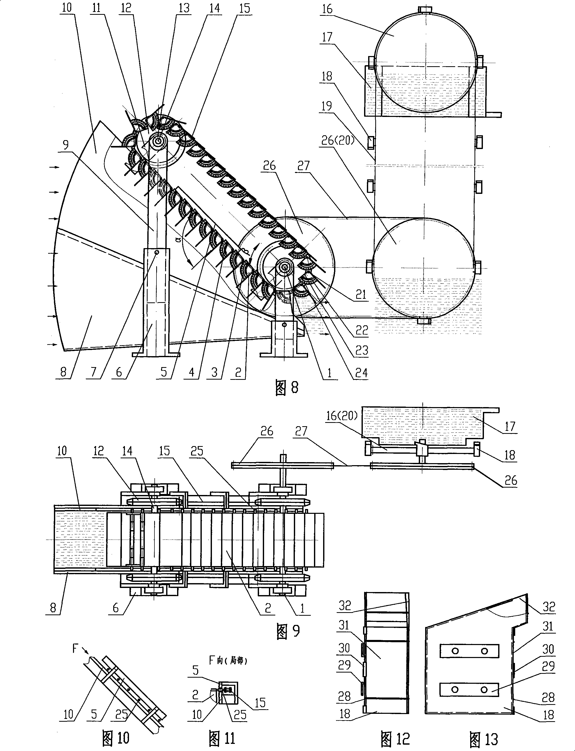
[0047] Such as Figure 8 , Figure 9 , Figure 10 , Figure 11 , Figure 12 , Figure 13 As shown, the present invention includes a water energy machine and a water lift driven by a different shaft of the water energy machine, and two drive sprockets 26, one coaxial with the drive sprocket shaft 1 of the water energy machine, and one with the water lift sprocket 20 coaxial, transmission chain 27 is arranged between two transmission sprockets 26, and water energy machine rotates, drives transmission sprocket 26 to rotate, and transmission sprocket 26 drives water lifting machine operation. All the other are the same as embodiment one.

Embodiment 3

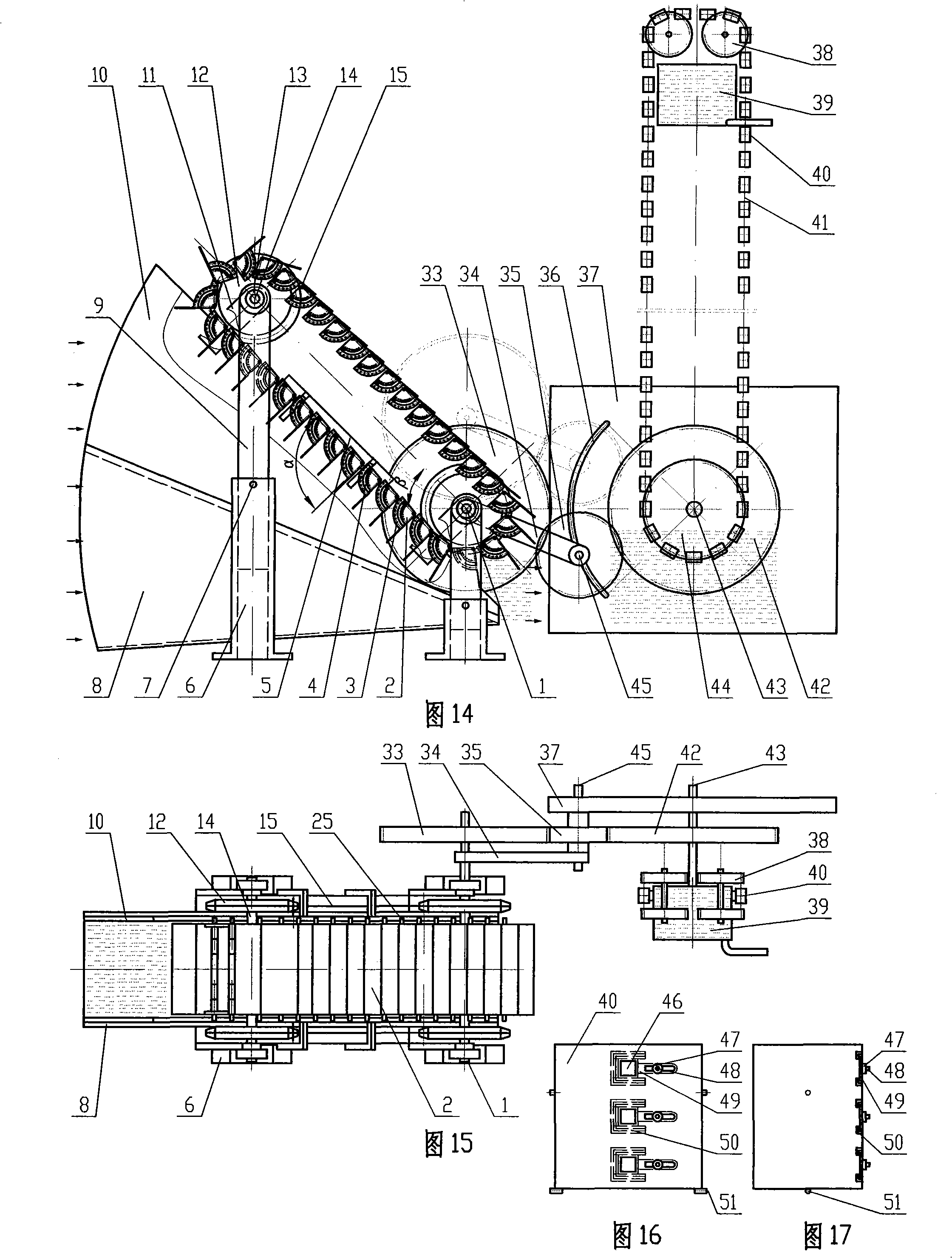
[0049] Such as Figure 14 , Figure 15 , Figure 16 , Figure 17 Shown, the present invention comprises water energy machine and double chain type water lifter and power transmission device, double chain type water lifter comprises two water lifting sprockets 44, four unloading sprockets 38, water collection tank 39, frame And have the frame plate 37 of arc groove 36, driven drive shaft 43 is installed on the frame plate 37 of band arc groove 36 coaxial with water-lifting sprocket wheel shaft, around water-lifting sprocket wheel 44 and unloading sprocket wheel 38 circles The water-lifting cylinder 40 with the push-pull plate water outlet 46 is hung on the closed double chain of the row; The clutch gear 35 on the clutch transmission shaft 45, the driven gear 42 coaxial with the water-lifting sprocket 44, the clutch connecting plate 34 is installed on the driving sprocket shaft 1 of the water energy machine, and the other end is installed on the clutch transmission shaft 45 ...


PUM


Abstract

The invention relates to agricultural irrigation and water conservancy equipments, in particular to an integrally adjustable automatic water elevator unit used for agricultural water conservancy. The water elevator unit mainly comprises a hydraulic power engine and a water elevator unit coaxially driven by the hydraulic power engine or a driving device and is characterized in that a sprocket shaft of the hydraulic power engine is installed on a lifting leg; a chain band plate is coaxially sheathed with an adjustable looseleaf bucket-shaped hydraulic plate; the hydraulic power engine comprisesa U-shaped underhole and baffles at both sides, which form a pressure conical volume cavity with the band plate; the water elevator is of single chain type; a water elevating sprocket wheel is coaxial with a drive sprocket axle of the hydraulic power engine; a closed single chain running around the water elevating sprocket wheel and a water discharging sprocket wheel is equipped with a looseleaf plastic cap and a water barrel at an opening by hanging. The water elevator unit can make full use of hydraulic power and can be easily adjusted. The hydraulic power engine, the water elevator mechanism and water elevating equipments can realize integral variable combination, in particular, the hydraulic power engine can be used by permutation and combination, thus increasing efficacy.

Description

technical field [0001] The invention relates to an agricultural irrigation and water conservancy equipment, in particular to a comprehensive adjustable automatic water lifting unit used in agriculture and water conservancy. Background technique [0002] In the current social production, agricultural irrigation, water conservancy equipment, and South-to-North Water Diversion projects, among the mechanical equipment that uses water flow to drive its own machine to lift water, the water energy utilization power of the water lifter is not very high, and the installation and use are not easy enough. Relatively large, the amount of water lifting is inconvenient to adjust, and the head of water lifting is not very high, so that the water lifting work cannot be effectively developed and utilized in a large area. [0003] The Chinese patent application with the application number 200510063101.4 discloses a technical solution of "water energy conversion automatic water lifting machine...

Claims


Application Information

Patent Timeline
Patent Type & Authority Patents(China)
IPC IPC(8): F03B13/00
Inventor 吕忠旺
Owner 吕忠旺
Why Eureka
Try Eureka