Dynamic balancing test device of rigid double-disk rotor
A technology of rigid rotors and experimental devices, applied in measurement devices, optical devices, instruments, etc., can solve problems such as over-completeness of special processing programs, increase in cost, and lack of independent thinking space, and achieve clear physical concepts, shortening distances, and reducing The effect of vibration interference
- Summary
- Abstract
- Description
- Claims
- Application Information
AI Technical Summary
Problems solved by technology
Method used
Image
Examples
Embodiment Construction
[0011] Embodiments of the present invention will be further described in detail below in conjunction with the accompanying drawings.
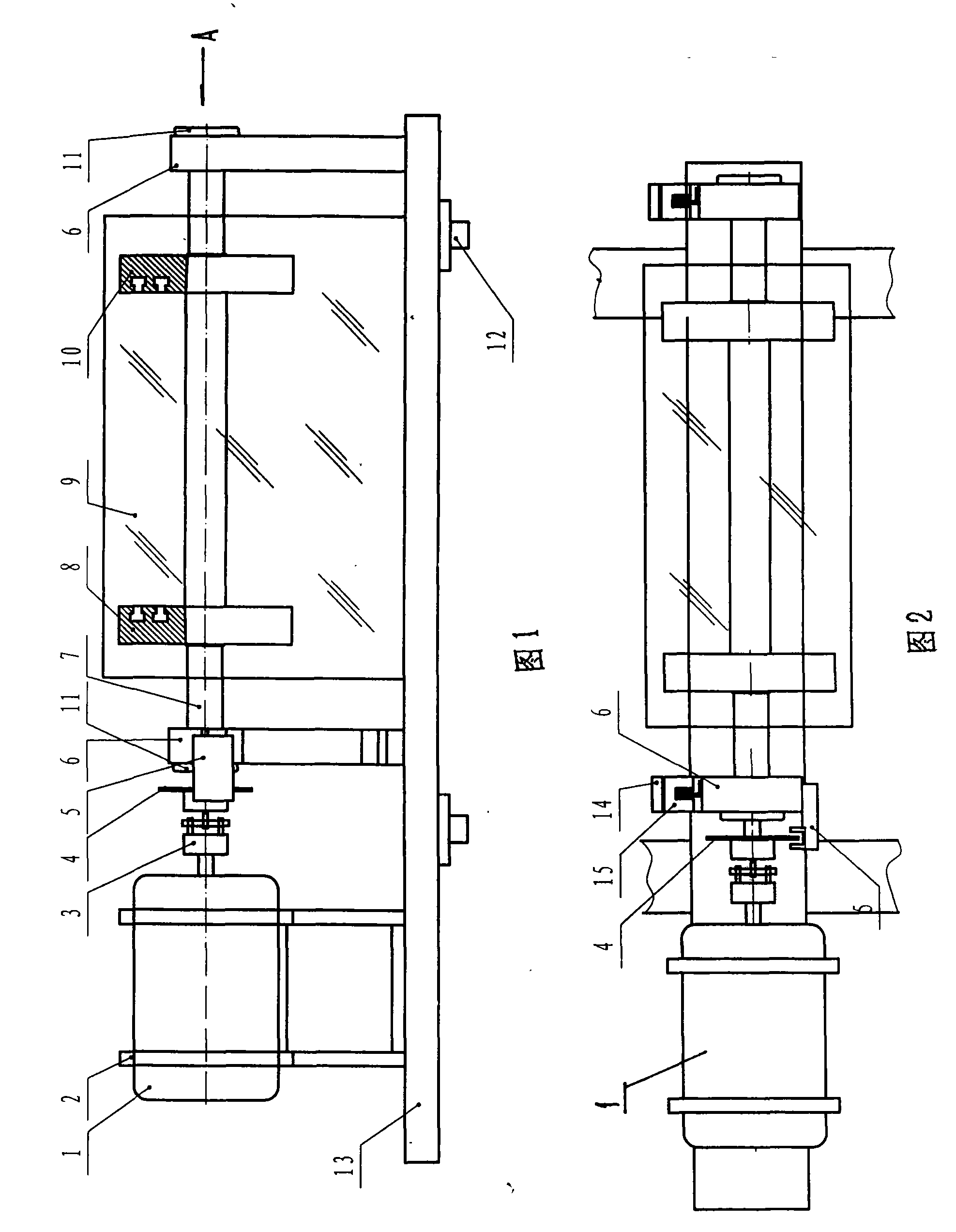
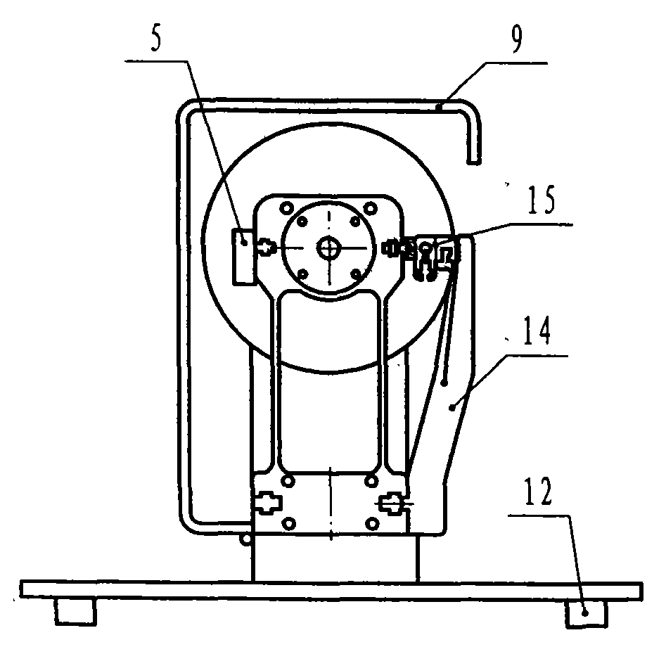
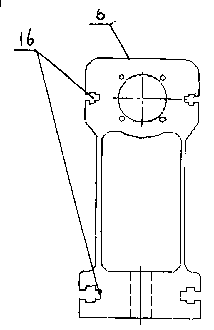
[0012] Depend on figure 1 one Figure 4 It can be seen that the bearing seat 11 is fixed on the elastic support 6, the lower end of the support arm 14 is fixedly connected with the elastic support 6, the photoelectric displacement sensor 15 is installed on the support arm 14, and is composed of the elastic support 6, the bearing seat 11, the support arm 14 and the photoelectric displacement sensor. The sensors 15 are jointly combined into an integral support, the rotating shaft 7 is installed on the elastic support 6 through the bearing seat 11, one end of the rotating shaft 7 is connected with the motor 1 by the coupling 3, the motor 1 is installed on the motor base 2, and the rotating shaft 7 is equipped with symmetrical The left and right balance plates 8,10, the outer buckles of the left and right balance plates 8,10 are equipped with tran...
PUM
 Abstract
Description
Claims
Application Information
 - R&D
- Intellectual Property
- Life Sciences
- Materials
- Tech Scout
- Unparalleled Data Quality
- Higher Quality Content
- 60% Fewer Hallucinations
Browse by: Latest US Patents, China's latest patents, Technical Efficacy Thesaurus, Application Domain, Technology Topic, Popular Technical Reports.
© 2025 PatSnap. All rights reserved.Legal|Privacy policy|Modern Slavery Act Transparency Statement|Sitemap|About US| Contact US: help@patsnap.com


