Novel inductive strain rosette
An inductive, strain rose technology, applied in the direction of electric/magnetic solid deformation measurement, electromagnetic measurement device, etc., can solve the problems of complex measurement circuit, small output of strain gage, and large influence of temperature change, and achieve the expansion of frequency response range, signal The effect of strong output and long service life
- Summary
- Abstract
- Description
- Claims
- Application Information
AI Technical Summary
Problems solved by technology
Method used
Image
Examples
Embodiment Construction
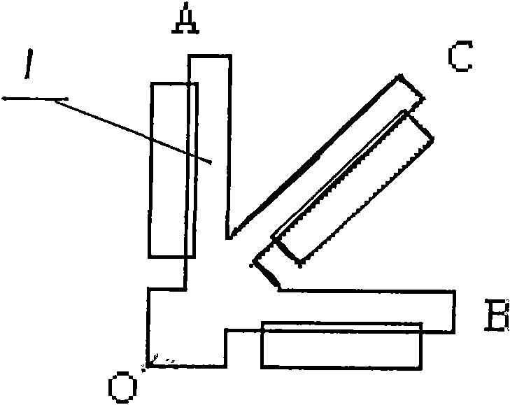
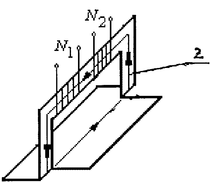
[0012] A new type of inductive rosette, using F with a thickness of 0.01-0.035mm e - Ni-based amorphous alloy flakes, cut into three arm bands 1 connected at the top, the angle between the three arm bands is 45°, cutting a "gate"-shaped breach on each arm band, and vertical It is folded to form a "gate"-shaped magnetic pole 2, and the measurement winding of the excitation winding is wound on each magnetic pole. The "gate"-shaped magnetic pole and the arm band body form a closed magnetic circuit. The arm band is rectangular, 20-30mm long, 10-18mm wide, and the height of the "gate" type magnetic pole is 5-8mm.
[0013] 1. Working principle
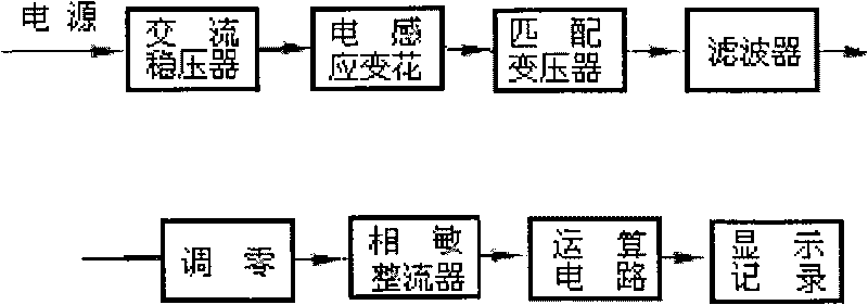
[0014] The inductive rosette of the present invention is based on the Villira effect of ferromagnetic materials. When in use, the strain rosette is welded on the surface of the workpiece to be measured for strain. When the principal strain direction is unknown, the rosette is welded in any direction, and the excitation coils on each armba...
PUM
 Abstract
Description
Claims
Application Information
 - R&D
- Intellectual Property
- Life Sciences
- Materials
- Tech Scout
- Unparalleled Data Quality
- Higher Quality Content
- 60% Fewer Hallucinations
Browse by: Latest US Patents, China's latest patents, Technical Efficacy Thesaurus, Application Domain, Technology Topic, Popular Technical Reports.
© 2025 PatSnap. All rights reserved.Legal|Privacy policy|Modern Slavery Act Transparency Statement|Sitemap|About US| Contact US: help@patsnap.com


