Check patentability & draft patents in minutes with Patsnap Eureka AI!

Plasma display device

A plasma and display device technology, applied in the direction of AC plasma display panels, circuit devices, static indicators, etc., can solve problems such as low brightness and high impedance

Inactive Publication Date: 2012-09-05
SAMSUNG SDI CO LTD
View PDF6 Cites 0 Cited by
  • Summary
  • Abstract
  • Description
  • Claims
  • Application Information

AI Technical Summary

Problems solved by technology

[0010] Thus, the scan electrodes connected to the outermost lines have high impedance and produce low luminance compared with the scan electrodes connected to the inner lines

Method used


Image

  • Plasma display device
  • Plasma display device
  • Plasma display device

Examples


Embodiment Construction

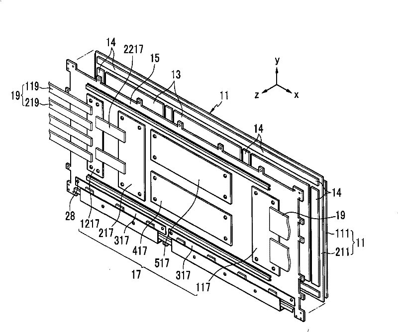
[0028] refer to figure 1 , the plasma display device includes a plasma display panel (PDP) 11 displaying images, a plurality of heat sinks 13 , a base 15 , a plurality of PCBs 17 , and a plurality of FPCs 19 .

[0029] Exemplary embodiments of the present invention relate to a coupling structure between the PDP 11 and other components. Therefore, a detailed description of the internal operation of the PDP is not required, and a detailed description thereof will be omitted here.

[0030] now refer to figure 1 , figure 2 and image 3 , the PDP 11 includes a front substrate 111 , a rear substrate 211 , sustain electrodes 31 , scan electrodes 32 and address electrodes 12 . Sustain electrodes 31 , scan electrodes 32 and address electrodes 12 are arranged to induce gas discharge in discharge cells 311 formed between front substrate 111 and rear substrate 211 .

[0031] At regions corresponding to the discharge cells 311, the address electrodes 12 cross the scan electrodes 32 t...


PUM


Abstract

The invention provides a plasma display device. The plasma display device includes a chassis base supporting a plasma display panel. A printed circuit board having a plurality of scan integrated circuits is mounted on the chassis base. Lines of a first flexible printed circuit and of a second flexible printed circuit connect the scan electrodes to the scan integrated circuits. The lines of each of the first and second flexible printed circuits include a first outer line and a second outer line at respective sides of each of the first and second flexible printed circuits, at least one inner line between the first outer line and the second outer line, and at least one dummy line at an outer side of the first outer line. The second outer line of the first flexible printed circuit is connected to the dummy line of the second flexible printed circuit.

Description

technical field [0001] The present invention relates to a plasma display device, and more particularly, to a plasma display device configured to prevent horizontal image streaking or lateral brightness difference caused by a brightness difference between scan electrodes. Background technique [0002] Generally, a plasma display device includes a plasma display panel (plasma display panel, PDP) for displaying images, a chassis base for supporting the PDP, and a plurality of chassis bases mounted on the base and connected to the PDP. Printed circuit board (PCB). [0003] The PDP generates plasma using gas discharge, excites phosphors using vacuum ultraviolet rays emitted from the plasma, and obtains images using red, green, and blue visible light generated when the excited phosphors remain stable. [0004] In order to induce gas discharge, the PDP includes address electrodes and display electrodes (eg, sustain electrodes and scan electrodes). In regions corresponding to the ...

Claims


Application Information

Patent Timeline
Patent Type & Authority Patents(China)
IPC IPC(8): G09G3/288H01J11/12H01J11/46H05K1/14G09G3/296
CPCG09G2330/06H05K1/0237H05K2201/10128H05K2201/09781H01J11/46H01J11/12G09G2300/0426H05K1/142H05K1/147H05K2201/09254G09G2320/0233G09G3/296G09G3/288H01J11/34
Inventor 吕宰英
Owner SAMSUNG SDI CO LTD
Features
  • R&D
  • Intellectual Property
  • Life Sciences
  • Materials
  • Tech Scout
  • Unparalleled Data Quality
  • Higher Quality Content
  • 60% Fewer Hallucinations
Learn More