Device for indicating failure of electric apparatus

A fault indication and electrical appliance technology, applied in switch status indication, circuit breaker parts, protective switch identification markings, etc. And other issues

Active Publication Date: 2009-09-16
ZHEJIANG CHINT ELECTRIC CO LTD
View PDF1 Cites 11 Cited by
  • Summary
  • Abstract
  • Description
  • Claims
  • Application Information

AI Technical Summary

Problems solved by technology

However, from the perspective of the storage process of the leakage information of the electrical device, if an electrical fault occurs, the reset of the indicator from the electrical fault indication state to the normal working state and the indication of the fault state after the electrical fault occurs must be realized by the handle drive. If the electrical fault is to be correctly indicated after the fault, the operating handle must be rotated to the breaking position quickly to ensure that the breaking speed of the handle is affected by the external force of the handle during the breaking process or the handle cannot return to the breaking state in time or delay returning to the breaking state , that is, the electrical fault indication information of the indicator cannot be locked, which will cause the electrical fault indicator to quickly return to the normal working indication state under the action of the reset torsion spring and cause a false indication. Therefore, the electrical fault indicator will not be able to realize The phenomenon of correct indication and wrong indication increases safety hazards when electricians carry out troubleshooting. This kind of safety hazard is not allowed to happen to terminal electrical equipment
In addition, the 98118669.6 patent, like other existing technologies, still has the characteristics of complex structure, many parts, large appearance and high production cost, which is not suitable for the production and manufacture of modularized terminal electrical appliances, especially small modularized low-voltage electrical products. and development requirements using

Method used


Image

  • Device for indicating failure of electric apparatus
  • Device for indicating failure of electric apparatus
  • Device for indicating failure of electric apparatus

Examples


Embodiment Construction

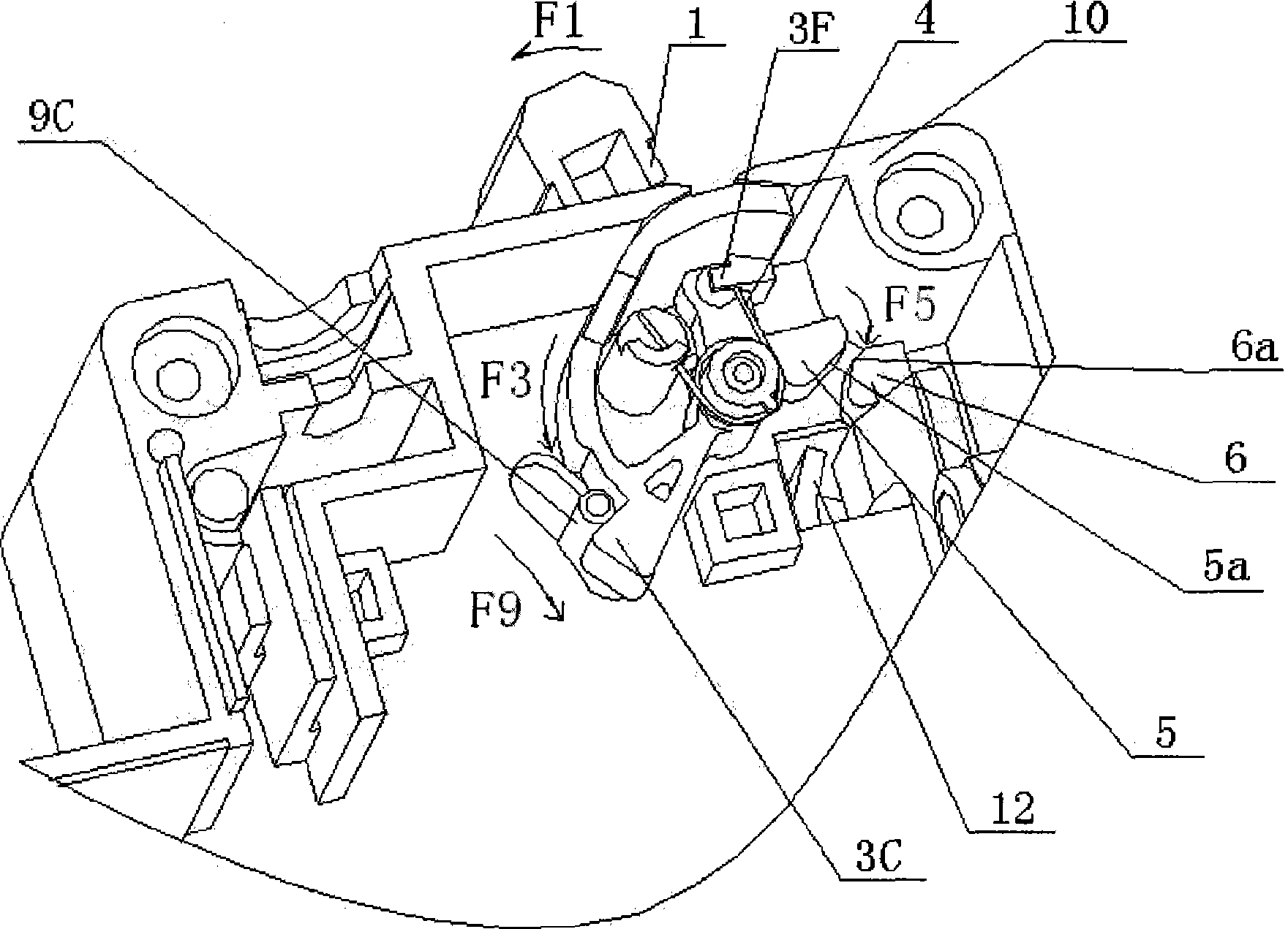
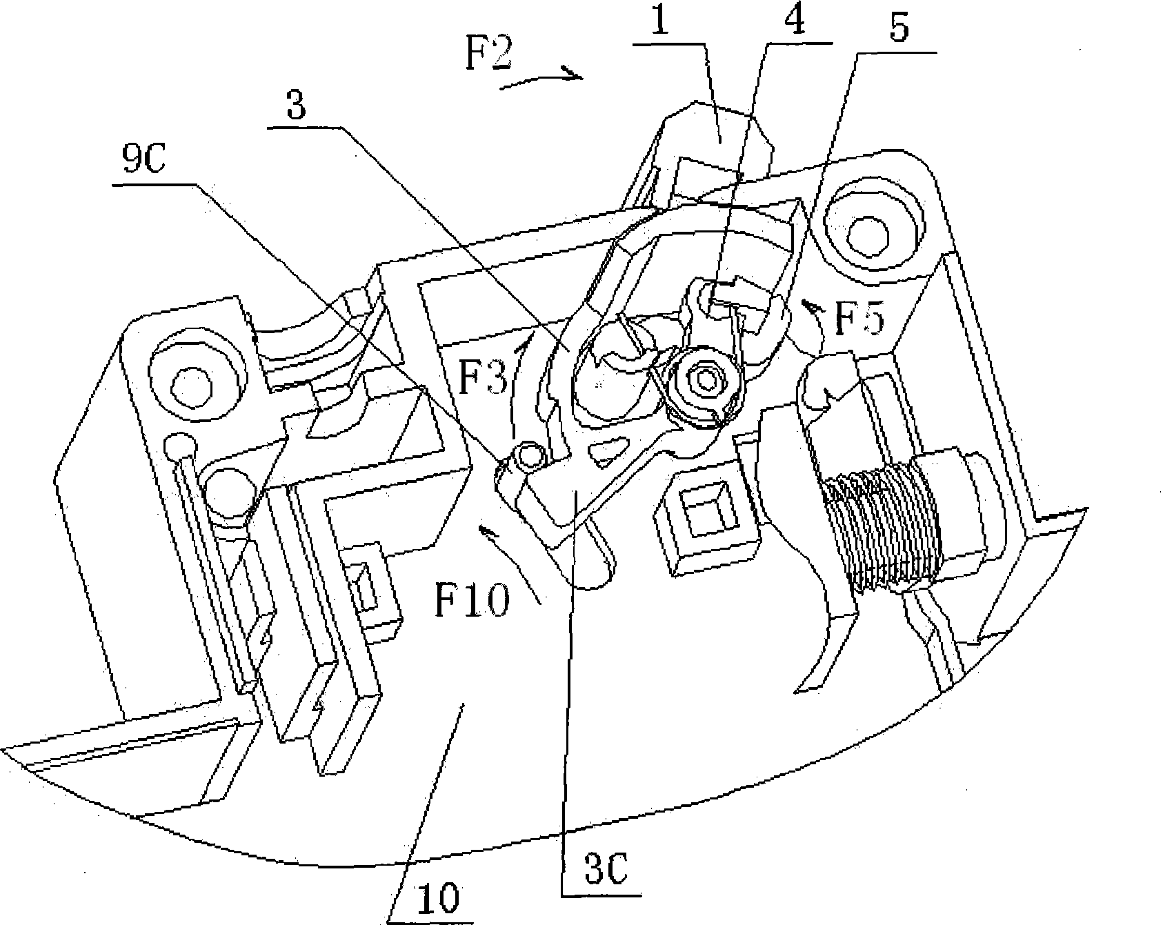
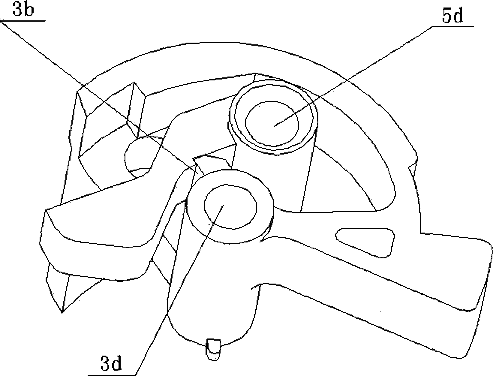
[0022] Attached below figure 1 -8, further describe the specific implementation of the electrical fault indicating device of the present invention. The electrical fault indicating device of the present invention is not limited to the specific description of the following embodiments.

[0023] Such as figure 1 and 2 As shown, the electrical fault indication device of the present invention is installed in the machine base 10, and the machine base 10 also includes: an operating mechanism (not shown in the figure) with an operating handle 1 for operating the electrical appliance on / off , the contact assembly (not shown in the figure) used to control the on / off of the main circuit, and the tripping mechanism used to control the quick tripping of the moving contact and the static contact from the closed state to the breaking state in the event of a fault (Fig. not shown). The tripping mechanism includes a fault detection system (not shown in the figure) and a tripping component ...


PUM


Abstract

A device for indicating the failure of an electric apparatus comprises an indicator, a fastener and a spring; the indicator and the fastener are arranged in the base of the electric apparatus; the indicator and the fastener are provided with a buckling-locking surface and a locking-buckling surface which are capable of realizing self-locking respectively; the indicator is provided with a white indicating surface representing a normal situation and a red indicating surface representing a failure situation; and the spring provides suitable self-locking force for the indicator and the fastener and provides a driving force for the indicator to be converted from a normal state to a failure state. When manually opening and closing the brake, the white indicating surface is always locked in the window of the base so as to indicate that the electric apparatus is in a normal state; when the electric apparatus fails and trips, the indicator and the fastener are released and rotate under the action of the elastic force of the spring so that other red indicating surfaces enter the window of the base so as to indicate that the electric apparatus is in a failure state; and the memory of the indicating state is not finished until the manual closing operation of the electric apparatus is carried out. The failure indication device has simple structure, good safety and reliability, low preparation cost and wide applications.

Description

technical field [0001] The invention relates to a fault indication device of a modularized terminal electric appliance, in particular to a device suitable for electrical fault indication. Background technique [0002] With the continuous improvement of the demand for terminal protection appliances in the electricity market, the miniaturization, diversification of functions and aesthetic appearance of its products have become the development trend of the new generation of electrical appliances. However, there is a contradiction between functional diversification and product miniaturization. When the function of the original product is added, it is likely to increase the volume of the product, and it is also likely to change the shape of the product. As for modular terminal appliances, their volume and shape are key indicators that directly affect the quality and use of the product. Therefore, the current design and production of modularized terminal appliances is always fac...

Claims


Application Information

Patent Timeline
Patent Type & Authority Applications(China)
IPC IPC(8): H01H73/12H01H71/06
Inventor 王先锋晏刚
Owner ZHEJIANG CHINT ELECTRIC CO LTD
Why Eureka
Try Eureka