Magnetic rotation conversion straight-moving mechanism

A direct-acting mechanism and magnetic rotation technology, applied in the direction of electromechanical devices, electric components, electromechanical transmission devices, etc., can solve the problems of low efficiency of crank linkage mechanism, complicated manufacturing of crankshaft, misuse of energy, etc., and achieve low cost and long life , high efficiency effect

Inactive Publication Date: 2009-09-16
刘新广
View PDF0 Cites 8 Cited by
  • Summary
  • Abstract
  • Description
  • Claims
  • Application Information

AI Technical Summary

Problems solved by technology

Therefore, the crank connecting rod mechanism is not only inefficient, but also causes some energy to be misused to damage the crankshaft, which is the fatal shortcoming of the crank connecting rod mechanism.
Furthermore, the crankshaft is complicated to manufacture and the cost is high

Method used


Image

  • Magnetic rotation conversion straight-moving mechanism
  • Magnetic rotation conversion straight-moving mechanism
  • Magnetic rotation conversion straight-moving mechanism

Examples


Embodiment 1

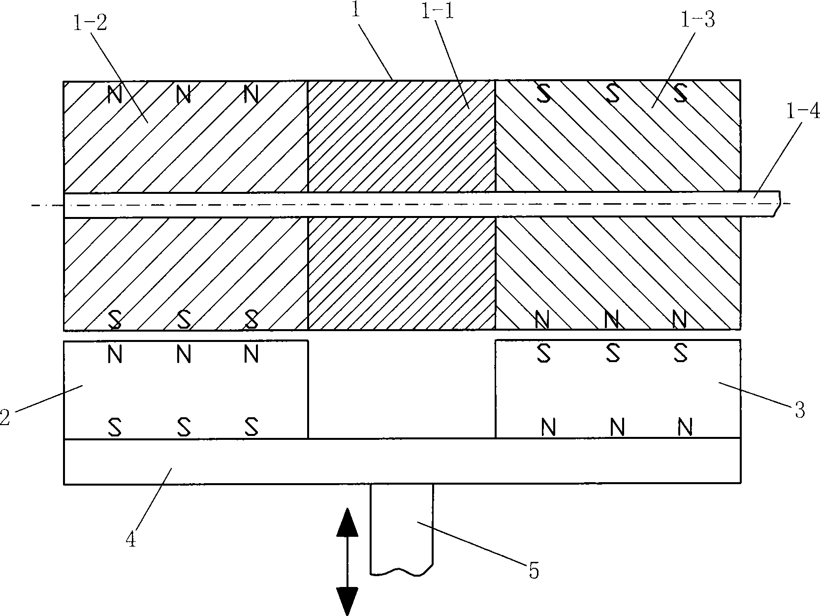
[0024] Embodiment one: if Figure 1 to Figure 3 Show. The magnetic wheel 1 is composed of a cylindrical permanent magnet 1-2, a cylindrical permanent magnet 1-3, and a non-magnetic cylinder 1-1 fixed on the rotating shaft 1-4. The cylindrical permanent magnet 1-2, the cylindrical permanent magnet 1-3 are all magnetized along the vertical direction, or first arbitrarily determine a plane that passes through the axis of the cylindrical permanent magnet 1-2 or cylindrical permanent magnet 1-3, and make the magnetization direction perpendicular to this plane during magnetization. Looking at the polarity of cylindrical permanent magnet 1-2 and cylindrical permanent magnet 1-3 is opposite (as figure 1 Shown), or cylindrical permanent magnet 1-2, cylindrical permanent magnet 1-3 are respectively spliced ​​by two half cylinders, and magnetization requirement is the same as aforementioned; Rotating shaft 1-4 is installed on frame ( (not drawn) among the figure); Place permanent magne...

Embodiment 3

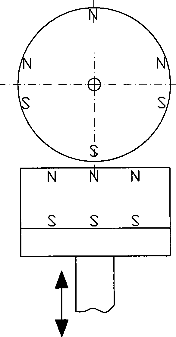
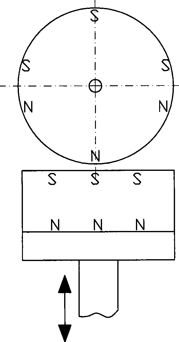
[0025] Embodiment three: as Figure 5 Show. Two vertically magnetized permanent magnets 7 are placed on the upper and lower sides of the magnetic wheel 6, and the permanent magnets 7 are connected with a linear moving part (not shown) with a coupling.

Embodiment 4

[0026] Embodiment four: as Figure 6 to Figure 8 Show. Magnetic wheel 1 is replaced by magnetic wheel 8, and permanent magnet 2 and permanent magnet 3 are replaced by polarity and permanent magnet 10 above permanent magnet 9. The magnetic wheel 8 consists of several pieces of tile-shaped permanent magnets 8-2 that are alternately magnetized along the radial polarity and several pieces of tile-shaped permanent magnets 8 that are alternately magnetized along the radial polarity that are fixed on the rotating shaft 8-4. -3. Magnetic cylinder 8-5, magnetic cylinder 8-6, and non-magnetic cylinder 8-1. It is required to look at the polarity of the inner and outer arcs of the tile-shaped permanent magnet 8-2 and the tile-shaped permanent magnet along the axial direction. The polarity of the inner and outer arcs of 8-3 is opposite (such as Figure 6 shown), tile-shaped permanent magnets 8-2 and tile-shaped permanent magnets 8-3 are at least two pieces each, or all tile-shaped perman...


PUM


Abstract

The invention provides a magnetic rotation conversion straight-moving mechanism. A magnetic wheel consists of a cylindrical permanent magnet and a non-magnetic cylinder that are fixedly connected on a rotation shaft; the cylindrical permanent magnet is filled with the magnetism in the vertical direction; alternatively, the cylindrical permanent magnet is assembled by two semi-cylinders; the magnetic wheel can also consist of a plurality of tile-shaped permanent magnets, magnetic-conductive cylinders and non-magnetic cylinders that are fixedly arranged on the rotation shaft and are alternatively filled with the magnetism in the radial direction with polarity; wherein the tile-shaped permanent magnet can be also replaced by a whole permanent magnetic ring divided into areas in the circumferential direction and alternatively filled with the magnetism in the radial direction with polarity; the rotation shaft is arranged on a frame by a bearing; a permanent magnet filled with the magnetism in the vertical direction is arranged below the magnetic wheel; the bottom surface of the permanent magnet is fixed with a magnetic-conductive plate; the center of the bottom surface of the magnetic-conductive plate is fixedly connected with a connecting rod; and the other end of the connecting rod is connected with a linear movement part. The magnetic rotation conversion straight-moving mechanism has no dead points, no friction, thus having the advantages of high efficiency, lubrication-free, energy-saving and environment-protection, long service life and low cost.

Description

technical field [0001] The invention relates to a mechanism for converting rotation into linear motion, in particular to a magnetic rotation conversion linear motion mechanism, which belongs to mechanical technology. Background technique [0002] The existing rotary and linear motion conversion mechanism is a well-known crank-link mechanism, which is mainly composed of connecting rod, slide block (or piston) and crankshaft. When the crank-link mechanism works, not only the friction force at the hinge is very large, but also when the slider moves along a straight line to the end of the stroke, the direction of movement of the connecting rod makes its long direction closer and closer to the direction of movement of the slider, and the connecting rod The driving torque to the crankshaft is getting smaller and smaller. When the slider moves to the end of the stroke, the driving torque of the connecting rod to the crankshaft is zero (called dead point), and a large bending destru...

Claims


Application Information

Patent Timeline
Patent Type & Authority Applications(China)
IPC IPC(8): H02K51/00
Inventor 刘新广
Owner 刘新广
Why Eureka
Try Eureka