Sheet metal parts rapid prototyping equipment

A technology for forming equipment and sheet metal parts, which is applied in the field of rapid prototyping equipment for sheet metal parts, and can solve problems such as failure to work normally, dead spots, and affecting equipment utilization.

Active Publication Date: 2015-10-28
SHENYANG AIRCRAFT CORP
View PDF4 Cites 0 Cited by
  • Summary
  • Abstract
  • Description
  • Claims
  • Application Information

AI Technical Summary

Problems solved by technology

In the past, the rapid prototyping equipment used the motor to drive the eccentric wheel and the crank connecting rod transmission structure. Every time it worked, it was necessary to adjust the stroke of the mold according to the thickness of the sheet metal part. If the adjustment is not correct, it will easily cause dead spots and cannot work normally, which will affect the quality of the equipment. utilization rate

Method used


Image

  • Sheet metal parts rapid prototyping equipment
  • Sheet metal parts rapid prototyping equipment
  • Sheet metal parts rapid prototyping equipment

Examples


Embodiment Construction

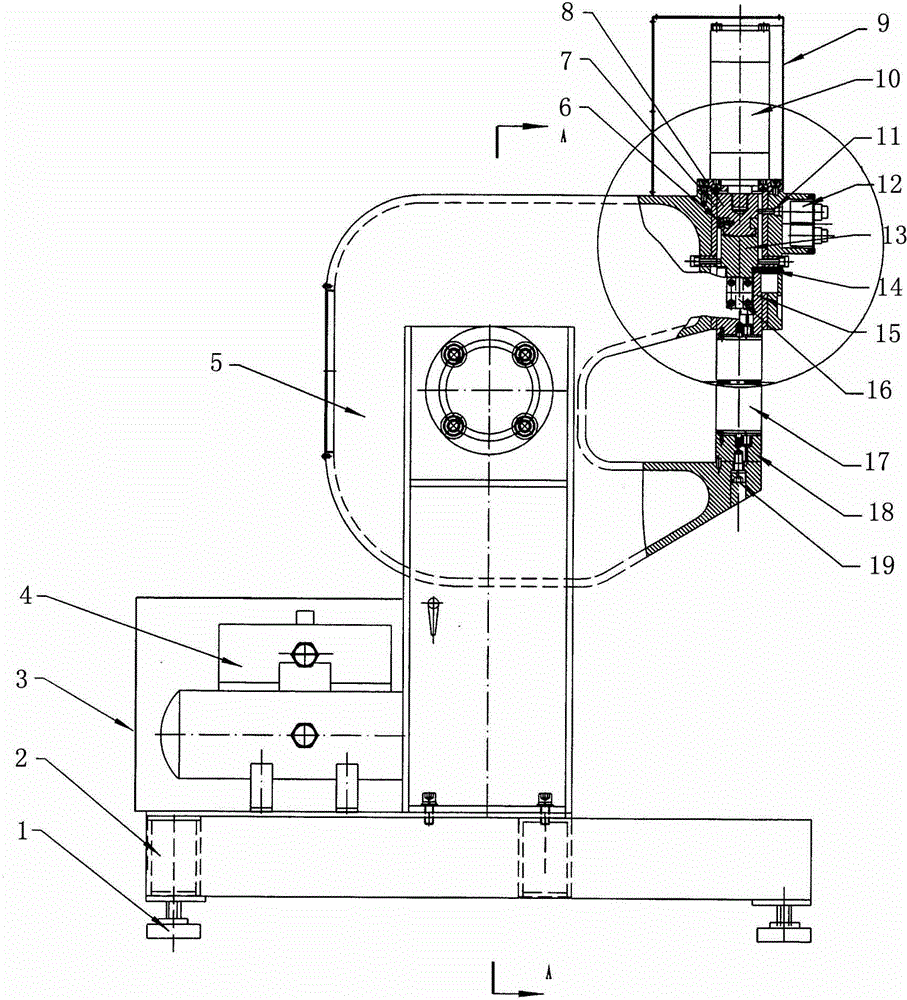
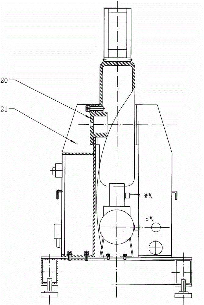
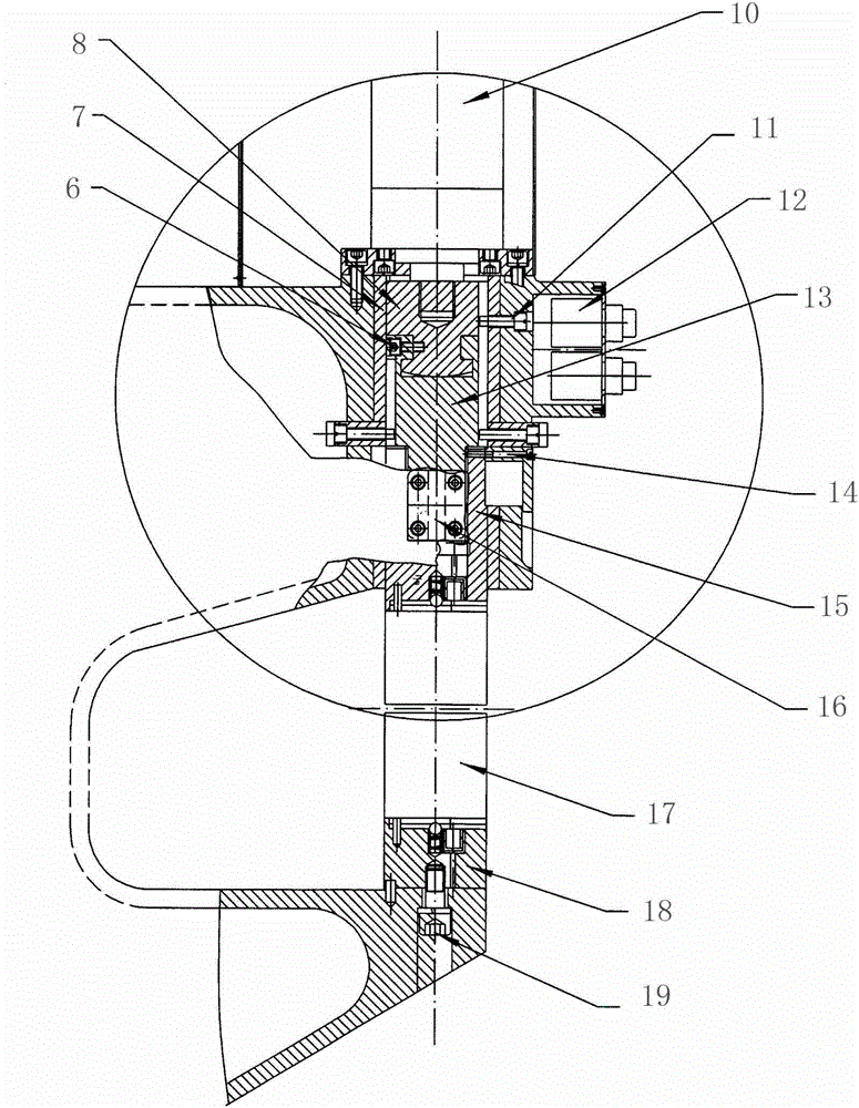
[0011] Such as Figure 1 to Figure 3 As shown, a rapid prototyping equipment for sheet metal parts is provided with a supercharger 4 above the base 2, a support 21 is symmetrically provided in front of the supercharger 4, and a connecting sleeve 20 is respectively provided at the inner end of the support 21. , the two connecting bushes 20 are jointly connected with the U-shaped bed 5; a gas-liquid conversion device 10 is arranged above the U-shaped bed 5, and the power input end of the gas-liquid conversion device 10 is connected with the supercharger 4, and the gas-liquid The output shaft of the conversion device 10 and the upper mold 20, while the upper mold 20 is located above the U-shaped groove opening of the U-shaped bed 5, and a mounting seat 18 is arranged below the U-shaped groove opening of the U-shaped bed 5. On the mounting seat 18 Connect the lower mold 17, the lower mold 17 is located below the U-shaped slot opening of the U-shaped bed 5, and corresponds to the p...


PUM


Abstract

The invention relates to a quick molding device for sheet metal parts. A supercharger is arranged above a base, supports are symmetrically arranged in front of the supercharger, connection shaft sleeves are arranged at the inner side ends of the supports, and the two connection shaft sleeves are connected with a U-shaped lathe bed together. A gas liquid conversion device is arranged above the U-shaped lathe bed, the power input end of the gas liquid conversion device is connected with the supercharger, an output shaft of the gas liquid conversion device is connected with an upper die, meanwhile the upper die is located above a U-shaped groove opening of the U-shaped lathe bed, an installation seat is arranged under the U-shaped groove opening of the U-shaped lathe bed and connected with a lower die, the lower die is located under the U-shaped groove opening of the U-shaped lathe bed, and the position of the lower die corresponds to that of the upper die. The quick molding device adopts the transmission structure that the gas liquid conversion device is directly connected with a connection shaft. Die journey is automatically adjusted in work, so that the metal sheet parts can be quickly molded.

Description

technical field [0001] The invention relates to a rapid prototyping equipment for sheet metal parts, which belongs to sheet metal processing equipment. Background technique [0002] Sheet metal parts are formed by stamping, stretching, shearing and other methods, and can also be processed by rapid prototyping equipment. In the past, the rapid prototyping equipment used the motor to drive the eccentric wheel and the crank connecting rod transmission structure. Every time it worked, it was necessary to adjust the stroke of the mold according to the thickness of the sheet metal part. If the adjustment is not correct, it will easily cause dead spots and cannot work normally, which will affect the quality of the equipment. usage rate. Contents of the invention [0003] The technical problem to be solved by the present invention is to provide a rapid prototyping equipment for sheet metal parts. The rapid prototyping device for sheet metal parts adopts a transmission structure i...

Claims


Application Information

Patent Timeline
Patent Type & Authority Patents(China)
IPC IPC(8): B30B1/38
Inventor 宋宝炜曹新华耿秋颖
Owner SHENYANG AIRCRAFT CORP
Why Eureka
Try Eureka