
Improved dual voltage control method and device thereof for matrix converters

A technology of a matrix converter and a control method, which is applied to the output power conversion device, the conversion of AC power input to AC power output, electrical components, etc., can solve the problems of large amount of calculation and difficult realization.

Active Publication Date: 2009-09-16
SOUTH CHINA UNIV OF TECH
View PDF0 Cites 12 Cited by
  • Summary
  • Abstract
  • Description
  • Claims
  • Application Information

AI Technical Summary

Problems solved by technology

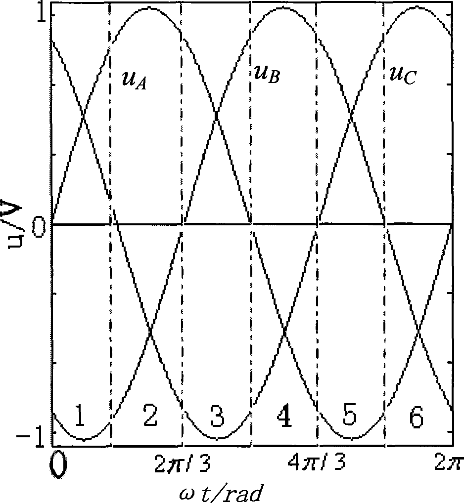
[0019] The purpose of the present invention is to overcome the above-mentioned deficiencies existing in the prior art, to provide an improved dual-voltage control method and its device for matrix converters, and to solve the problems that the general dual-voltage control system has a large amount of calculation and is difficult to implement. The purpose of this invention is to reduce the calculation amount of the system by re-dividing the input and output voltage sectors and giving a unified duty ratio calculation formula, so as to facilitate the realization of software programming and improve the efficiency and real-time performance of the program.

Method used


Image

  • Improved dual voltage control method and device thereof for matrix converters
  • Improved dual voltage control method and device thereof for matrix converters
  • Improved dual voltage control method and device thereof for matrix converters

Examples


Embodiment Construction

[0068] The implementation of the present invention will be described in further detail below in conjunction with the accompanying drawings.

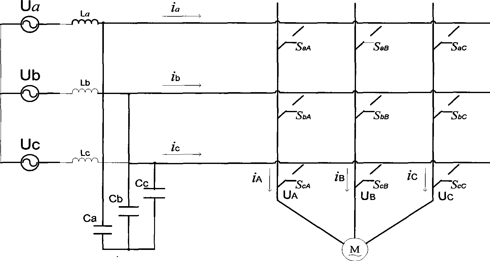
[0069] Such as figure 1 As shown, the main circuit topology of the matrix converter consists of 9 switch tubes SaA, SaB, SaC, SbA, SbB, SbC, ScA, ScB, and ScC arranged in a matrix. The three-phase power supplies Ua, Ub, Uc are connected to the input end of the three-phase matrix converter through the input filter circuit, and the motor M is connected to the output end of the three-phase matrix converter as a load. The input filter circuit is composed of filter inductors La, Lb, and Lc. And filter capacitors Ca, Cb, Cc, the output voltage of the matrix converter is U A , U B , U C . The three-phase input currents of the matrix converter are i a , I b , I c , The three-phase output current is i A , I B , I C .

[0070] By controlling the on and off of each switch tube, the three-phase output is connected to any phase of the input through a tw...


PUM


Abstract

The invention provides an improved dual voltage control method and a device thereof for matrix converters. The method comprises the following steps: re-dividing voltage sectors; carrying out custom calculation on variables required by duty ratio and ranking the variables; calculating the duty ratio of the matrix converter system according to the general calculation formula of the duty ratio; obtaining the duty ratio of each two-way power switch based on the corresponding relation between the duty ratio of the matrix converter system and that of each two-way power switch in a switch matrix; calculating the turn-on time of each two-way power switch in real time after the duty ratio of each two-way power switch is multiplied by the switch cycle, and realizing on-off control of the matrix converter. The device comprises an input voltage sampling unit, a DSP control circuit, a CPLD switch gate circuit, a detecting unit of output current direction and a drive circuit. The invention simplifies the system switch combination and the system has little amount of calculation, thus improving the efficiency and real-time and being suitable for application in controlling the matrix converters in the field of AC variable frequency speed regulating.

Description

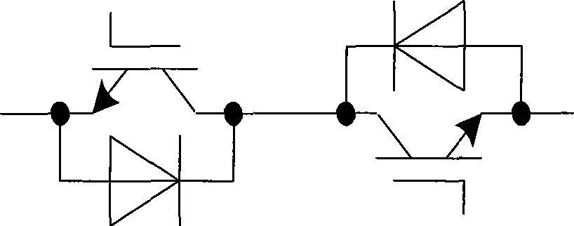
Technical field [0001] The invention belongs to matrix converter control technology, and specifically relates to an improved dual voltage control method and device for matrix converters. Background technique [0002] Matrix converter is an AC-AC direct converter with excellent input and output characteristics. It has the advantages that traditional AC-DC-AC inverters can’t match: it eliminates the intermediate DC link; the output voltage has less low-order harmonic content; the output frequency Not affected by input frequency; energy can flow in both directions, suitable for four-quadrant operation of AC motors. [0003] The three-phase-three-phase matrix converter is named after 9 bidirectional power switches SaA, SaB, SaC, SbA, SbB, SbC, ScA, ScB, ScC arranged in a matrix, and the three-phase input voltage is U a , U b And U c , The three-phase output voltage is U A , U B And U C , Its circuit topology such as figure 1 Shown. Among them, SaA is a bidirectional power switch tha...

Claims


Application Information

Patent Timeline
IPC IPC(8): H02M5/257
Inventor 杨苹郑木桂
Owner SOUTH CHINA UNIV OF TECH
Learn More