Method for identifying remote ONU down-linked terminal equipment in PON system automatically

A technology for automatic identification and terminal equipment, which is applied in the field of Ethernet passive optical network systems, and can solve the problems that PON network systems cannot be realized.

Inactive Publication Date: 2009-09-16
FENGHUO COMM SCI & TECH CO LTD
View PDF0 Cites 32 Cited by
  • Summary
  • Abstract
  • Description
  • Claims
  • Application Information

AI Technical Summary

Problems solved by technology

[0004] The technical problem to be solved by the present invention is to solve the problem that the PON network system cannot realize comprehensive ne

Method used


Image

  • Method for identifying remote ONU down-linked terminal equipment in PON system automatically
  • Method for identifying remote ONU down-linked terminal equipment in PON system automatically
  • Method for identifying remote ONU down-linked terminal equipment in PON system automatically

Examples


Embodiment Construction

[0022] The purpose of the present invention is to provide a method for an Ethernet passive optical network system to automatically identify remote ONU downstream terminal equipment, so as to better improve the PON system resource management function according to the actual operation needs of the PON system. The method provided by the present invention can be used as an important component of the unified management of PON system resources to realize automatic discovery and identification of remote ONU downstream equipment, and further realize its management.

[0023] The present invention will be described in detail below with reference to the accompanying drawings.

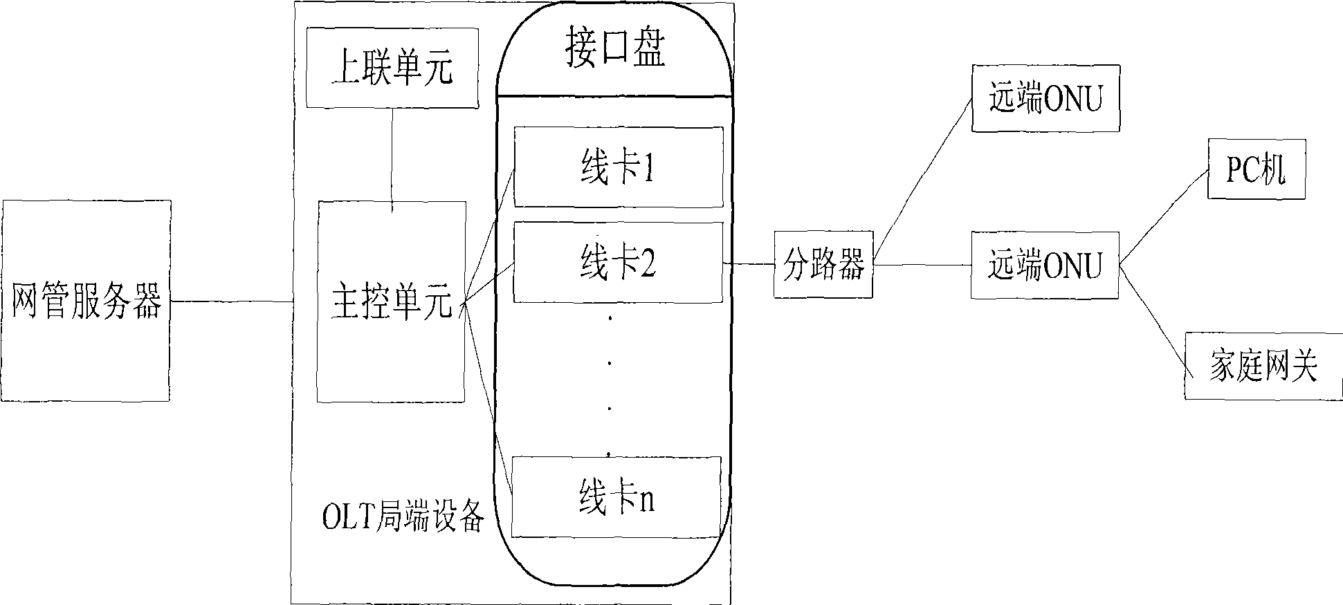
[0024] figure 1 Schematic diagram of the structure of the PON system, such as figure 1 As shown, the PON system includes PON central office equipment (OLT), a network management server (network management center) connected to the PON central office equipment, an optical splitter ODN connected to the PON central off...


PUM


Abstract

The invention discloses a method for identifying remote ONU down-linked terminal equipment in PON system automatically which includes steps as follows: S1, forward planning MAC address range of a home gateway in the down-linked terminal equipment; S2. ONU accessing register to OLT automatically and obtaining authorization; S3. PON access disc obtaining MAC address of ONU end down-linked equipment, and judging the end down-linked equipment whether being home gateway or PC according with the address whether falling into the MAC address range forward planned in step S1, then reporting the down-linked equipment type to a main control unit; S4. the main control unit reporting the down-linked equipment type to a network management center. The method is uses as an important component part for processing uniform management to PON system resource which can realize finding and identifying the remote ONU down-linked equipment automatically, accordingly, realize management thereof.

Description

Technical field [0001] The invention relates to an Ethernet passive optical network system, in particular to a method for automatically identifying remote ONU downlink terminal equipment in a PON system. Background technique [0002] Passive Optical System (PON) is a new type of optical fiber access network technology. It adopts a point-to-multipoint structure, passive optical fiber transmission, and provides multiple services on Ethernet. It uses PON technology at the physical layer, Ethernet protocol at the link layer, and uses the PON topology to achieve Ethernet access. Therefore, it combines the advantages of PON technology and Ethernet technology: low cost; high bandwidth; strong scalability, flexible and fast service reorganization; compatibility with existing Ethernet; convenient management, etc. [0003] In the traditional PON network management framework, each district office is often used to independently build a dedicated network for network management, and the end of...

Claims


Application Information

Patent Timeline
IPC IPC(8): H04Q11/00H04B10/08H04L12/24
Inventor 李凌李必锴
Owner FENGHUO COMM SCI & TECH CO LTD
Why Eureka
Try Eureka