
Sealing arrangement of a piezoactuator for a fuel injection valve of an internal combustion engine

A piezoelectric actuator and fuel injection valve technology, which can be applied to fuel injection devices, special fuel injection devices, machines/engines, etc. problem, to achieve the effect of improving long-term stability and high permeability

Active Publication Date: 2013-06-05
VTESCO TECH GMBH
View PDF4 Cites 0 Cited by
  • Summary
  • Abstract
  • Description
  • Claims
  • Application Information

AI Technical Summary

Problems solved by technology

[0003] In known seals, the adhesive force and thus the sealing effect, which are limited by the material properties of the seal, are defective
There is also a risk that this adhesion will weaken as the material relaxes over time
Finally, it is also a disadvantage that the seal requires installation space on the side of the head unit opposite the piezo actuator

Method used


Image

  • Sealing arrangement of a piezoactuator for a fuel injection valve of an internal combustion engine
  • Sealing arrangement of a piezoactuator for a fuel injection valve of an internal combustion engine

Examples


Embodiment Construction

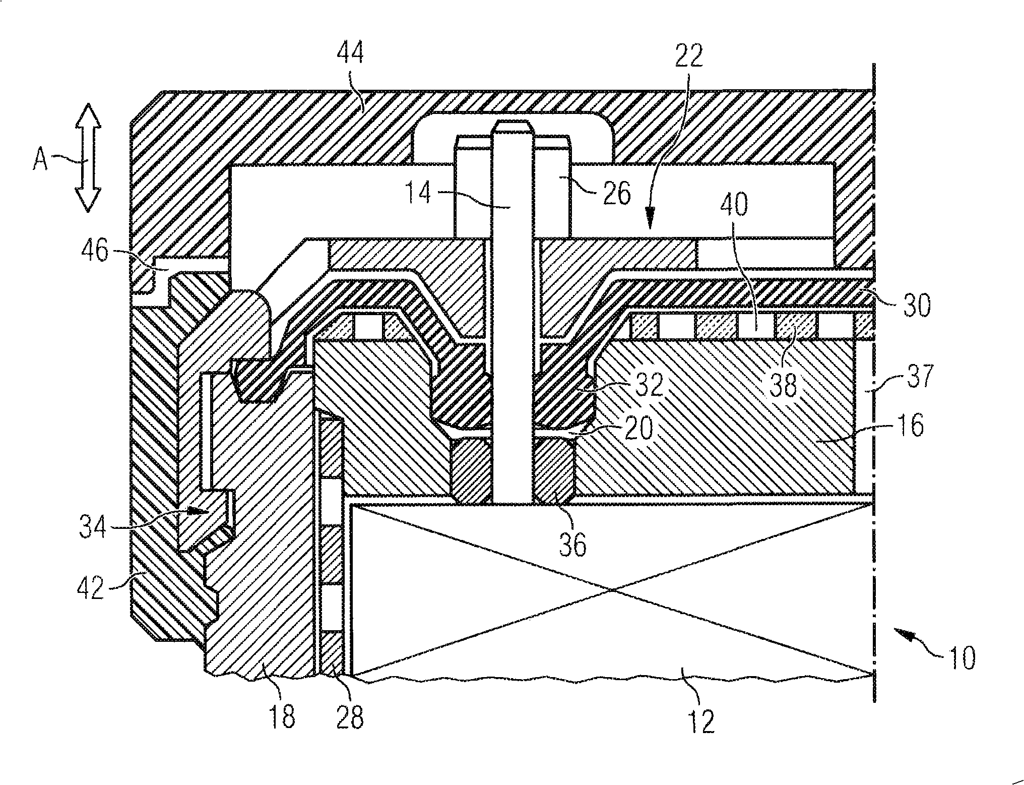
[0032] figure 1 One embodiment of a seal for a piezoelectric actuator 12 within a piezoelectric driver, generally designated 10, is shown.

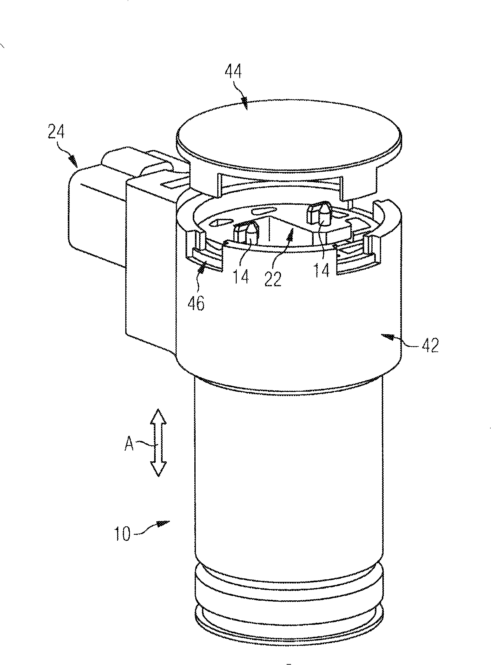
[0033] figure 2 A piezo drive 10 for actuating an injection valve of a fuel injector of an internal combustion engine (for example a diesel injector of a “common rail” injection system) is shown. In the installed state, the piezoelectric actuator 10 is shown with figure 1 The fuel injector is formed together with the injection valves arranged below the piezoelectric actuator 10 but not shown in this figure.

[0034] As far as the basic structure of the fuel injector is concerned, reference is made, for example, to known designs such as those described in DE 199 56 256 B4, DE 100 07 175 A1 and DE 10 2004 042 353 A1.

[0035] look again figure 1 , for brevity, figure 1 Only half of the (left side) of the axial section (axial A) is shown, and one of the two connecting pins 14 protruding from the piezoelectric actuator 12 can be seen from...


PUM


Abstract

A sealing arrangement of a piezoactuator (12) for a fuel injection valve of an internal combustion engine, has connecting pins (14) projecting out of the piezoactuator (12) and a head arrangement (16, 18) placed on to the piezoactuator (12), which is provided with openings (20) for the penetration of the connecting pins (14), wherein a liquid-tight sealing element (30) abuts against the outer surfaces of the connecting pins (14) on one side and also against the head arrangement (16, 18) on the other. In order to ensure a reliable seal with this arrangement, in particular also over extended periods of time, the sealing element (30) abuts against the outer surfaces of the connecting pins (14) located inside the openings (20), and sealing element sections (32) located inside the openings (20) are radially compressed in the openings.

Description

technical field [0001] The invention relates to a sealing device according to the preamble of claim 1 . Background technique [0002] Such a device is known, for example, from DE 10 2004 042 353 A1. In the known sealing arrangement, the sealing is achieved by means of an elastomer sealing washer, by means of which a dome-shaped sealing section protruding upwards from the plane of the washer bears sealingly against the peripheral surface of the connecting pin section, which The pin section protrudes from the hole of the top plate which is fitted on the piezoelectric actuator. The adhesive force for providing the sealing effect is here preferably produced by the elastic tension of the elastomeric gasket material. [0003] In known sealing arrangements, the adhesive force and thus the sealing effect, which are limited by the material properties of the seal, are deficient. There is also a risk that this adhesion will weaken as the material relaxes over time. Finally, it is a...

Claims


Application Information

Patent Timeline
IPC IPC(8): F02M51/00F02M51/06
CPCF02M2200/16F02M51/0603F02M51/005F02M63/0057F02M2200/9015F02M55/007
Inventor M·昂鲁C·朱姆斯特鲁尔
Owner VTESCO TECH GMBH
Learn More