Portal type wind turbine

A wind turbine and door-type technology, which is applied in the field of door-type wind turbines, can solve the problems of wind dispersion and low wind utilization rate, and achieve the effect of sealing, high efficiency and reducing resistance

Inactive Publication Date: 2009-09-23
乔君旺
View PDF0 Cites 0 Cited by
  • Summary
  • Abstract
  • Description
  • Claims
  • Application Information

AI Technical Summary

Problems solved by technology

[0003] In order to solve the problem that the wind power of the existing wind turbines is dispersed in an open environment and the utilization rate of wind power is low, a portal type wind turbine is provided

Method used


Image

  • Portal type wind turbine
  • Portal type wind turbine
  • Portal type wind turbine

Examples


Embodiment 1

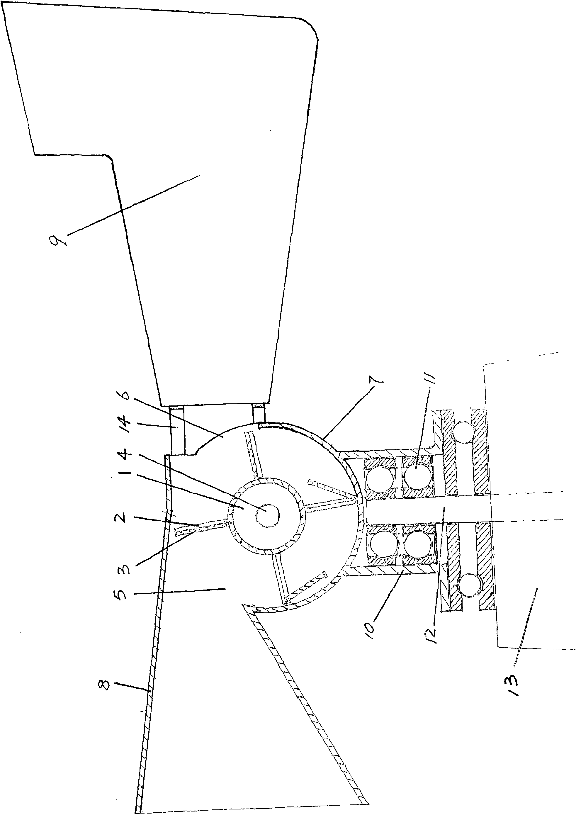
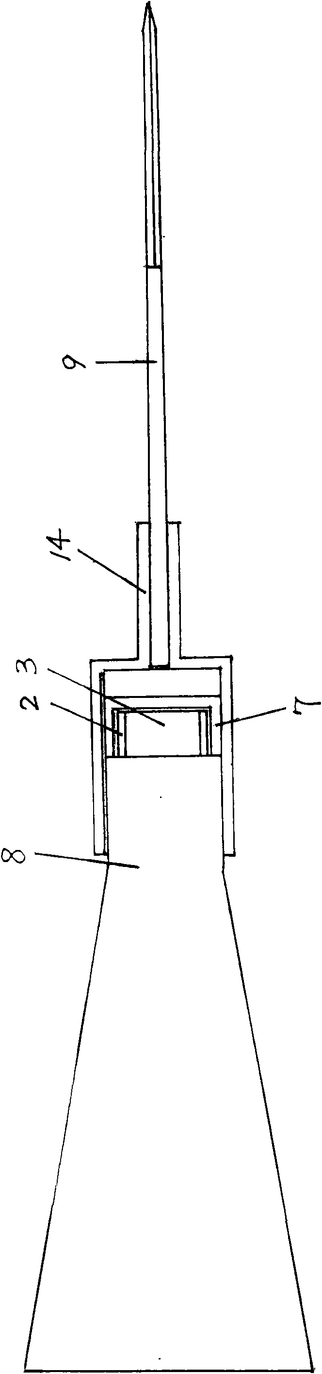
[0028] Example 1: as figure 1 , figure 2 As shown, two vertical sections of the portal frame 2 are fixed on the outer circumferences of the two wheel webs 1 . A wheel shell 7 is arranged outside the wind wheel, and the rotating shaft 4 is installed on the wheel shell 7. The upper part of the wheel shell 7 is relatively provided with an air inlet 5 and an air outlet 6, and the air inlet 5 is connected as one with the small end of the tapered wind bucket 8. The air outlet 6 is connected with a wind direction plate 9, and the wind direction plate 9 can be connected with the wheel housing 7 through a connecting rod 14, and the length of the connecting rod 14 is determined according to the overall balance.

[0029] The bottom of the wheel housing 7 is provided with a bearing sleeve 10 rotatably mounted on the carrier 13 . The bearing sleeve 10 is installed on the rotating shaft 12 through the bearing 11 , and the rotating shaft 12 is installed on the carrier 13 .

[0030] Durin...

Embodiment 2

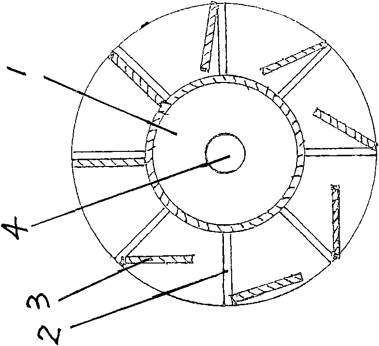
[0032] Example 2: as image 3 As shown, a number of wheel slots are evenly distributed on the spoke plate 1 relative to the wheel shaft 4, and the vertical section of the door-shaped frame 2 of the wind wheel is inserted into the wheel slots.

Embodiment 3

[0033] Embodiment 3: Two wind direction plates 9 are arranged at the air outlet of the wheel shell 7, and the two wind direction plates 9 are directly integrated with the wheel shell 7.


PUM


Abstract

The invention belongs to a wind turbine, in particular to a portable type wind turbine, which solves the problem that the wind power of the existing wind turbine dispersedly does work under the open environment, so the utilization rate of the wind power is low. The portable type wind turbine comprises a wind wheel which comprises a wheel shaft, both ends of which are provided with two spoke plates; a plurality of portable type frameworks are arranged between the two spoke plates and are composed of a horizontal segment and two vertical segments; the two vertical segments of each portable type framework are respectively fixed on the two spoke plates; the portable type frameworks are equispaced opposite to the wheel shaft; the top of each portable type framework is articulated with a door leaf. The portable type wind turbine has the following beneficial effects of wind power utilization containerization, concentrated wind power, centralized wind power speed acceleration, plate surface blowing whole piece, wheel shell closing efficiency, and switch reduction resistance.

Description

technical field [0001] The invention belongs to wind turbines, in particular to a portal type wind turbine. Background technique [0002] Existing wind turbines all include a plurality of blades, one end of the blades is installed on a rotating shaft, and the wind pushes the blades to drive the rotating shaft to rotate, thereby converting wind energy into mechanical energy. The wind force of this kind of wind turbine disperses work in an open environment, so that the utilization rate of wind power is greatly limited. SUMMARY OF THE INVENTION [0003] The invention provides a portal type wind turbine in order to solve the problem that the wind force of the existing wind turbine is scattered and works in an open environment and the utilization rate of the wind force is low. [0004] The present invention adopts following technical scheme to realize: [0005] A portal type wind turbine, comprising a wind wheel, the wind wheel includes a wheel shaft, characterized in that sp...

Claims


Application Information

Patent Timeline
Patent Type & Authority Applications(China)
IPC IPC(8): F03D5/00F03D11/00F03D80/00
CPCY02E10/722Y02E10/72Y02E10/70
Inventor 乔君旺
Owner 乔君旺
Why Eureka
Try Eureka