
Real-time traffic signal control method under condition of sight obstruction

A real-time traffic and signal control technology, applied in the direction of traffic signal control, etc., can solve problems such as the inability to clear sight obstacles, low reliability and security, and insufficient intuitive information, so as to improve safety and orderly passing, and better Pertinence and adaptability, the effect of scientific control principles

Inactive Publication Date: 2009-09-23
SOUTHEAST UNIV
View PDF0 Cites 11 Cited by
  • Summary
  • Abstract
  • Description
  • Claims
  • Application Information

AI Technical Summary

Problems solved by technology

However, traffic safety problems usually occur on the road section where the driver's line of sight is obstructed, especially on the curve. When the traffic volume increases to a certain extent, and the sight obstacle cannot be cleared in a short time, it is necessary to provide the driver with more reliable information on the road ahead, so as to improve the safety of driving on the road section where the line of sight is obstructed, especially whether the opposite direction is When a vehicle is approaching
[0003] In reality, mirrors are generally used to provide the driver with traffic information on the other side of the curve on roads or curves where the line of sight is obstructed. The information provided by the mirrors is generally not intuitive enough, and when affected by environmental visibility conditions and driving Due to many factors such as the strength level of the road crew, the reliability and security are very low. Once a traffic accident occurs on these road sections, the degree of the accident is relatively serious, and it is easy to cause long-term traffic jams.

Method used


Image

  • Real-time traffic signal control method under condition of sight obstruction
  • Real-time traffic signal control method under condition of sight obstruction
  • Real-time traffic signal control method under condition of sight obstruction

Examples


example

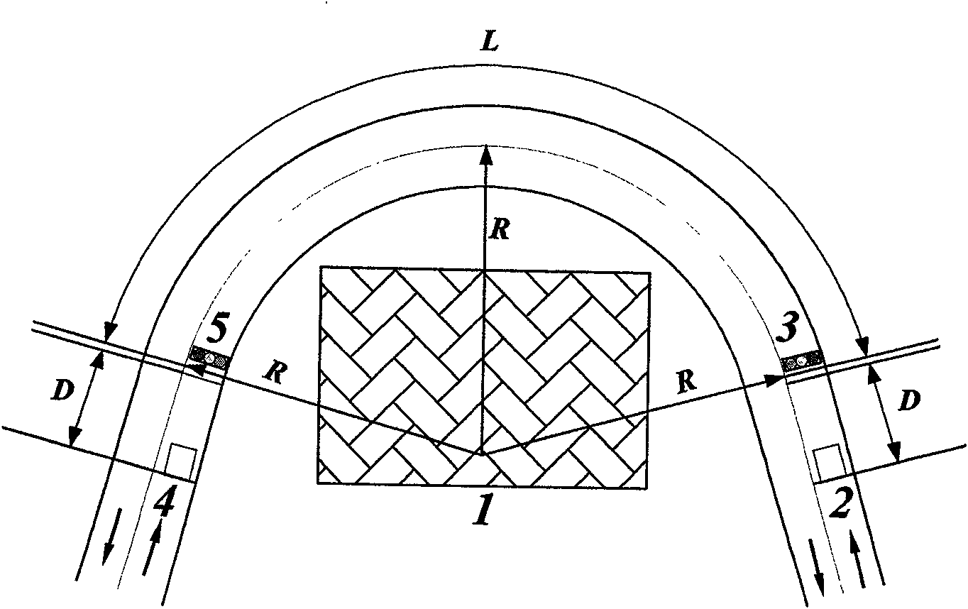
[0061] Select a typical line of sight obstacle road, such as the attached Figure 4 As shown, the basic parameters are as follows: the radius R of the circular curve of the line of sight obstacle section is 35m, L is 80m, and the maximum arrival rate of the vehicle arrival detector is q max is 0.20 vehicles / s, the distance D between the detector and the stop line is 25m, the lateral force coefficient μ is 0.06, the lateral slope i of the road surface is 0.08, and the vehicle speed V on the section between the detector and the stop line is 0 It is 35km / h. According to the formula 1.1-1.4, the calculation result is as follows:

[0062] a. Minimum green light time G min :

[0063] G min = 3.6 ( L V l + D V 0 ) = ...


PUM


Abstract

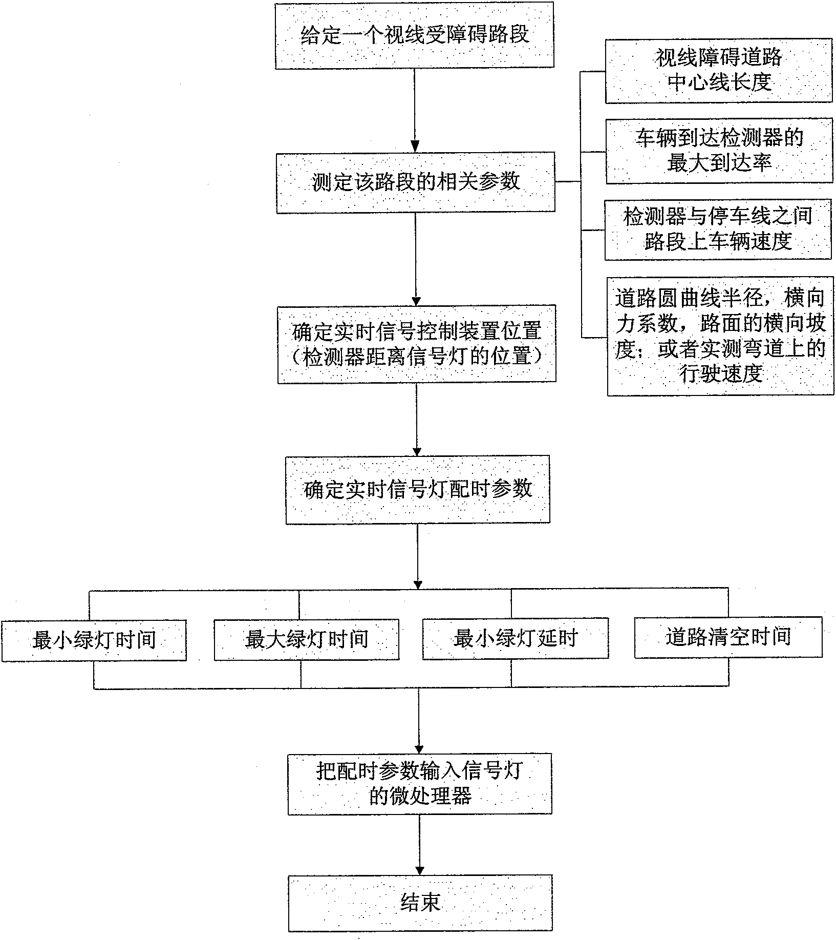
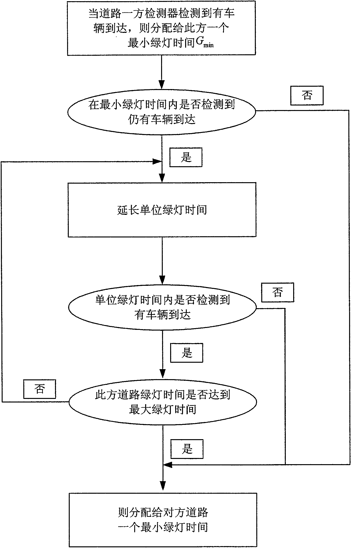
The invention relates to a real-time traffic signal control method under condition of sight obstruction, which comprises the following steps: origin and destination of a sight obstruction section of a sight obstruction road are respectively provided with a first signal lamp 3 and a second signal lamp 5 which are oppositely arranged, a first section and a second section which are connected with the origin and the destination of the sight obstruction section are respectively provided with a first vehicle detector 2 and a second vehicle detector 4 which are used for measuring and obtaining the length L of the center line of the sight obstruction section, the maximum arrival factor q max of a vehicle to the detectors, the distance D between the detectors and a stop line, the cornering ratio Mu, the cross slope i of the road surface, the vehicle velocity V0 on the section between the detectors and the stop line, and the radius R of curve of the sight obstruction section of the road or the actual measured running velocity Vl on the sight obstruction section; the minimum green time G min of the sight obstruction section, the green delay time Delta per unit, the maximum green time G max and the curve clearing time Tc of real-time signal control time assignment parameters are respectively calculated; and the obtained real-time signal control time assignment parameters are input into a microprocessor, and are transmitted to the signal lamps through the microprocessor.

Description

technical field [0001] The invention relates to a real-time traffic signal control method on a curve on a road or a road section obstructed by obstacles (such as buildings, mountains or heavy fog), and belongs to the field of road traffic control. Background technique [0002] At present, a wide range of real-time traffic signal control devices mainly include traffic flow detection devices and signal light devices. The detection of driving speed enables the signal light device on the intersection to give more optimized signal timing control, as well as the safety control of the upper speed limit of the road, so as to reduce the delay and accident rate of vehicles at the intersection, so as to ensure the safety and efficiency of vehicles form. However, traffic safety problems usually occur on the road section where the driver's line of sight is obstructed, especially on the curve. When the traffic volume increases to a certain extent, and the sight obstacle cannot be cleare...

Claims


Application Information

Patent Timeline
IPC IPC(8): G08G1/07
Inventor 谢之权陈峻罗振科白桦
Owner SOUTHEAST UNIV
Learn More