Check patentability & draft patents in minutes with Patsnap Eureka AI!

Circular cylinder generator

A generator, ring technology, applied in the direction of machines/engines, electrical components, electromechanical devices, etc., can solve the problems of energy loss, insufficient utilization of generator mechanical energy, and inability to increase the power generation of generators, so as to improve energy utilization. , the effect of increasing power generation

Active Publication Date: 2012-08-22
佛山市国能宏基投资有限公司
View PDF4 Cites 0 Cited by
  • Summary
  • Abstract
  • Description
  • Claims
  • Application Information

AI Technical Summary

Problems solved by technology

This type of traditional generator has insurmountable shortcomings in its structure, which leads to insufficient utilization of the mechanical energy of the generator, resulting in energy loss, which limits the power generation of the generator and cannot increase

Method used


Image

  • Circular cylinder generator
  • Circular cylinder generator
  • Circular cylinder generator

Examples


Embodiment Construction

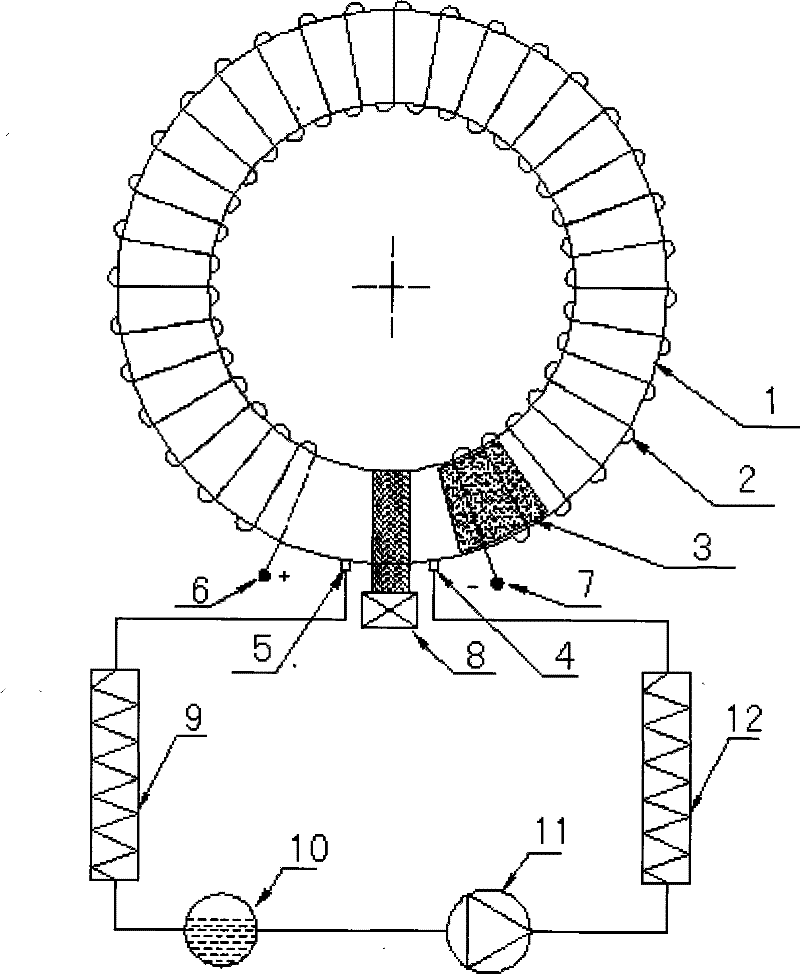
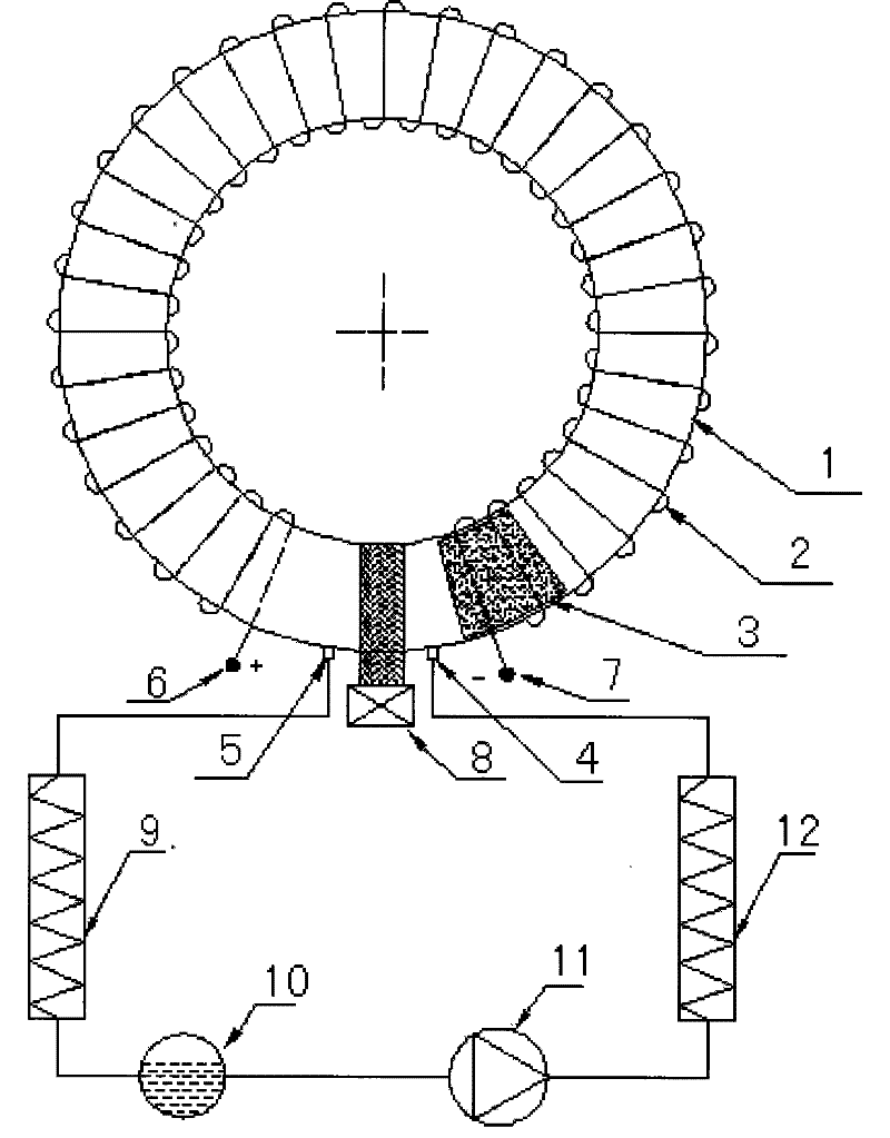
[0010] The following comparison is attached figure 1 The present invention will be described in detail.

[0011] Such as figure 1 As shown, a metal coil 2 is first wound on the outer periphery of the annular cylinder 1, and the terminals 6 and 7 are respectively drawn out at both ends of the coil 2, and a permanent piece that can be cyclically slid is placed in the inner cavity of the annular cylinder 1. Magnet 3 is fitted with a control valve 8 at that section of the annular cylinder 1 in the middle of the two terminals. The control valve 8 mainly controls the opening and closing of the inner cavity of the annular cylinder 1. When the control valve 8 is opened, the entire inner cavity of the annular cylinder 1 is annularly connected. When the control valve 8 is closed, the entire inner cavity of the annular cylinder 1 is not connected. The inner cavity is cut off with the control valve as the starting and ending point. Air inlet 4 and exhaust port 5 are provided on the cyl...


PUM


Abstract

The invention relates to a generator, in particular to a circular cylinder generator. A circular cylinder is wound with a metal coil on the outer wall to serve as a stator, and a permanent magnet is made into a block which is suitable to be arranged in the inner cavity of the circular cylinder and capable of sliding to serve as a rotor. A magnet block is pushed by internal energy for the automatically expansion of an expending agent to continuously and circularly slide in the inner cavity of the circular cylinder, electromagnetic power is generated by a magnet circuit and a circuit which mutually carry out electromagnetic induction, and the electromagnetic power is led out through a connecting terminal and connected in a loop so as to generate electrical current and realize the power generation function.

Description

Technical field: [0001] The invention belongs to a generator, in particular to an annular cylinder generator. technical background: [0002] A generator is a mechanical device that converts other forms of energy into electricity. The generator is composed of stator, rotor, end cover and bearing, among which the core component stator is composed of stator core, wire winding, frame and other structural parts fixing these parts, and the rotor is composed of rotor core (or magnetic pole, magnetic Choke) windings, guard rings, center rings, slip rings, fans and shafts and other components. The bearing and the end cover connect and assemble the stator and the rotor of the generator, so that the rotor can rotate in the stator and do the movement of cutting the magnetic force line, thereby generating an induced potential, which is drawn out through the terminal and connected to the circuit to generate a current. Generators are widely used in industrial and agricultural production,...

Claims


Application Information

Patent Timeline
Patent Type & Authority Patents(China)
IPC IPC(8): F01K7/00H02K35/02H02K7/18
Inventor 郎风
Owner 佛山市国能宏基投资有限公司
Features
  • R&D
  • Intellectual Property
  • Life Sciences
  • Materials
  • Tech Scout
  • Unparalleled Data Quality
  • Higher Quality Content
  • 60% Fewer Hallucinations
Learn More