Supercharge Your Innovation With Domain-Expert AI Agents!

Dimming coupled circuit matched with filaments of aerial discharge fluorescent lamp

A technology of gas discharge and fluorescent lamps, applied in electric light sources, light sources, electrical components, etc., can solve the problems of power consumption, temperature rise, energy waste, etc.

Inactive Publication Date: 2009-09-23
CHUAN SHIH INDAL
View PDF0 Cites 0 Cited by
  • Summary
  • Abstract
  • Description
  • Claims
  • Application Information

AI Technical Summary

Problems solved by technology

However, when the damping resistor is working, it often emits a lot of heat, consumes the power of the power supply, and causes a waste of energy.
In addition, it will further increase the temperature in the plastic cavity of the gas discharge fluorescent lamp

Method used


Image

  • Dimming coupled circuit matched with filaments of aerial discharge fluorescent lamp
  • Dimming coupled circuit matched with filaments of aerial discharge fluorescent lamp

Examples


Embodiment Construction

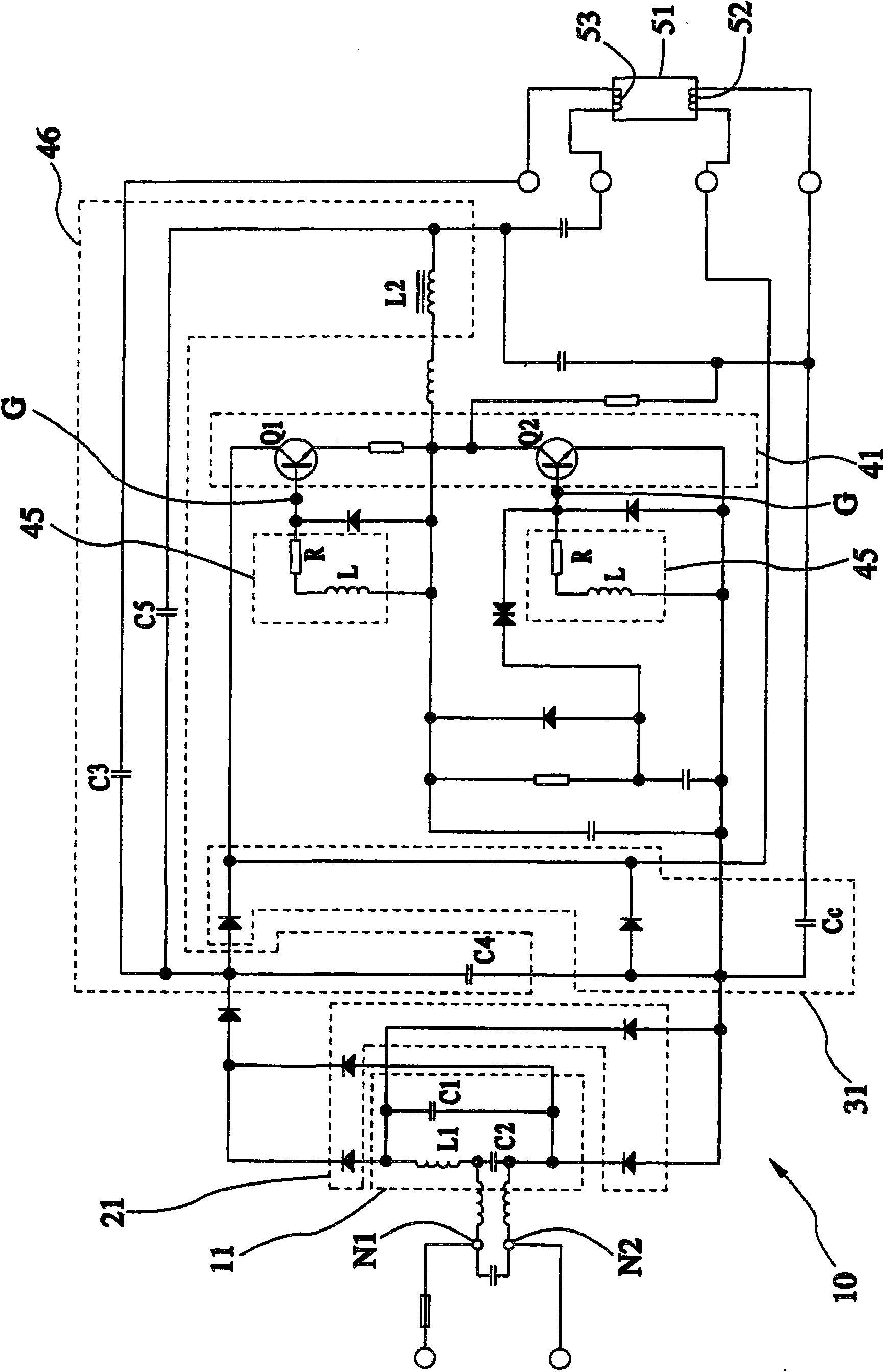
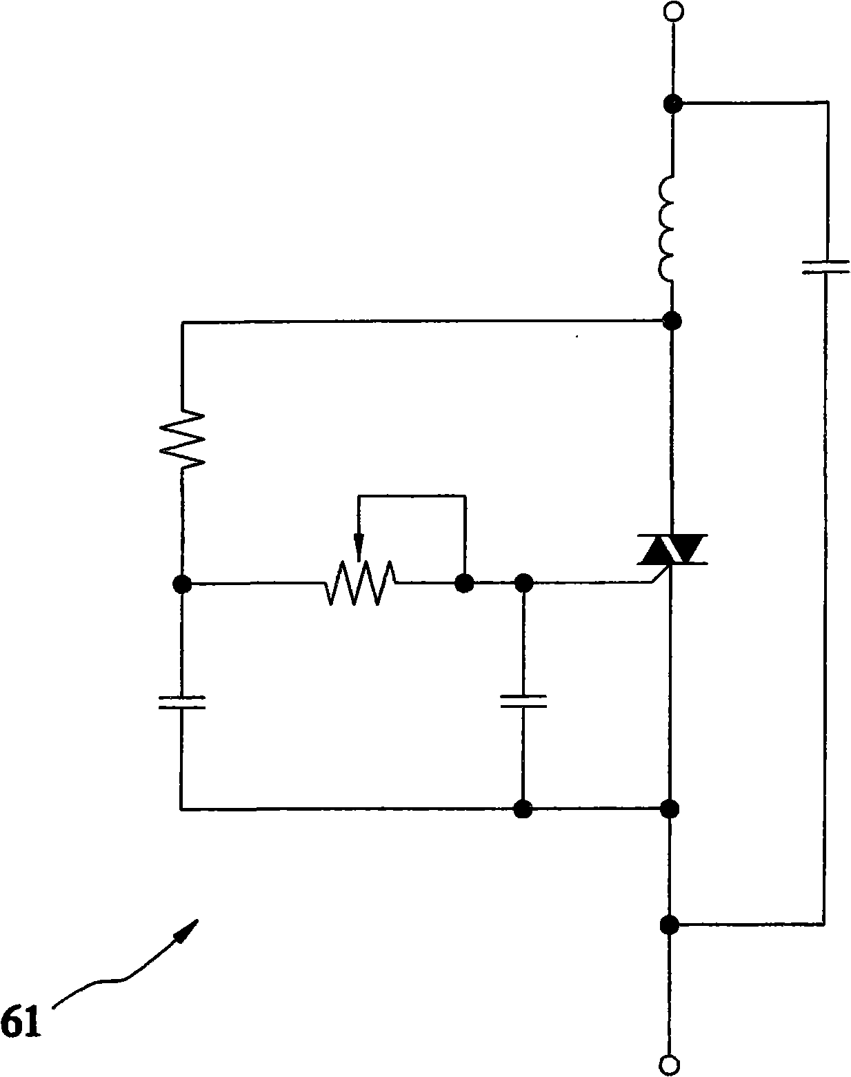
[0045] Such as figure 1 As shown, a dimming matching circuit 10 for a hot cathode gas discharge fluorescent lamp provided by a preferred embodiment of the present invention can be used for matching with a standard dimmer 61 to perform dimming function. The gas discharge of the matching filament The fluorescent lamp dimming matching circuit 10 is mainly composed of a resonant unit 11, a rectifying unit 21, a charging circuit 31, a half-bridge output unit 41, and a lamp 51, wherein:

[0046] The resonant unit 11 has a first capacitor C1 and a second capacitor C2 connected in series, and a first inductor L1 connected in parallel to the series combination of the first capacitor C1 and the second capacitor C2.

[0047] The rectifying unit 21 is connected to the resonant unit 11 for converting AC power into DC power. In this embodiment, the rectification unit 21 is a bridge rectifier.

[0048] The charging circuit 31 has a charging capacitor Cc connected to the rectifying unit 21 ...


PUM


Abstract

A dimming coupled circuit matched with filaments of an aerial discharge fluorescent lamp comprises a resonant unit, a rectifying unit, a charging circuit and a half-bridge output unit, wherein the resonant unit is mainly provided with a first capacitor and a second capacitor which are connected in series with each other, and also is provided with an inductor which is connected in parallel with a tandem compound combination of the first capacitor and the second capacitor; the rectifying unit is connected with the resonant unit and is used for converting alternating current into direct current; the charging circuit is provided with at least one charging capacitor and is connected with the rectifying unit; and the half-bridge output unit is mainly provided with two electric control switches which are connected in series with each other and is connected with the charging circuit, and each electric control switch is provided with a control end which is connected with an oscillating unit. The dimming coupled circuit is characterized in that a light tube is connected with the charging circuit; the inside of the light tube is provided with two filaments, wherein one end of one filament is connected with one end of power input passing through the charging capacitor; and by directly heating the filaments, the dimming coupled circuit solves the problem of color break-up because the light tube is connected with the electric control switches, and has the effects of energy re-utilization and avoiding temperature rise.

Description

technical field [0001] The invention relates to a gas discharge fluorescent lamp, in particular to a dimming and matching circuit for a gas discharge fluorescent lamp with a filament. Background technique [0002] Press, currently known commercially available dimmable gas discharge fluorescent lamps, or dimmable electronic rectifiers for fluorescent tubes, usually use IC (integrated circuit) chips with electronically controlled switches (such as bidirectional silicon The commercially available standard dimmer that controls TRIAC) is used for dimming control, and its circuit contains multiple capacitors, resistors, and inductors. The gas discharge fluorescent lamp is usually composed of a lamp tube and a plastic cavity, and the circuit is placed in the plastic cavity. [0003] However, in the process of dimming, when the electronically controlled switch is triggered to conduct, the charging of the capacitor will generate a pulse current of several amperes, which will interac...

Claims


Application Information

Patent Timeline
Patent Type & Authority Applications(China)
IPC IPC(8): H05B41/298H05B41/38
Inventor 叶昭钦
Owner CHUAN SHIH INDAL
Features
  • R&D
  • Intellectual Property
  • Life Sciences
  • Materials
  • Tech Scout
  • Unparalleled Data Quality
  • Higher Quality Content
  • 60% Fewer Hallucinations
Learn More