Master cylinder

A master cylinder and cylinder technology, applied in the direction of hydraulic brake transmission, etc., can solve the problems of affecting sliding performance and poor seating performance, and achieve the effect of ensuring sliding performance

Active Publication Date: 2009-09-30
HITACHI LTD
View PDF4 Cites 3 Cited by
  • Summary
  • Abstract
  • Description
  • Claims
  • Application Information

AI Technical Summary

Problems solved by technology

As a result, the retainer interferes with the arc-shaped wall surface of the outermost circumference of the inner bottom of the piston, and its seating performance is not good, and the spring assembly is tilted as a whole, which may cause the piston to generate a jamming torque and affect the sliding performance

Method used


Image

  • Master cylinder
  • Master cylinder
  • Master cylinder

Examples


no. 1 example

[0030] A master cylinder according to a first embodiment of the present invention will be described below with reference to the drawings.

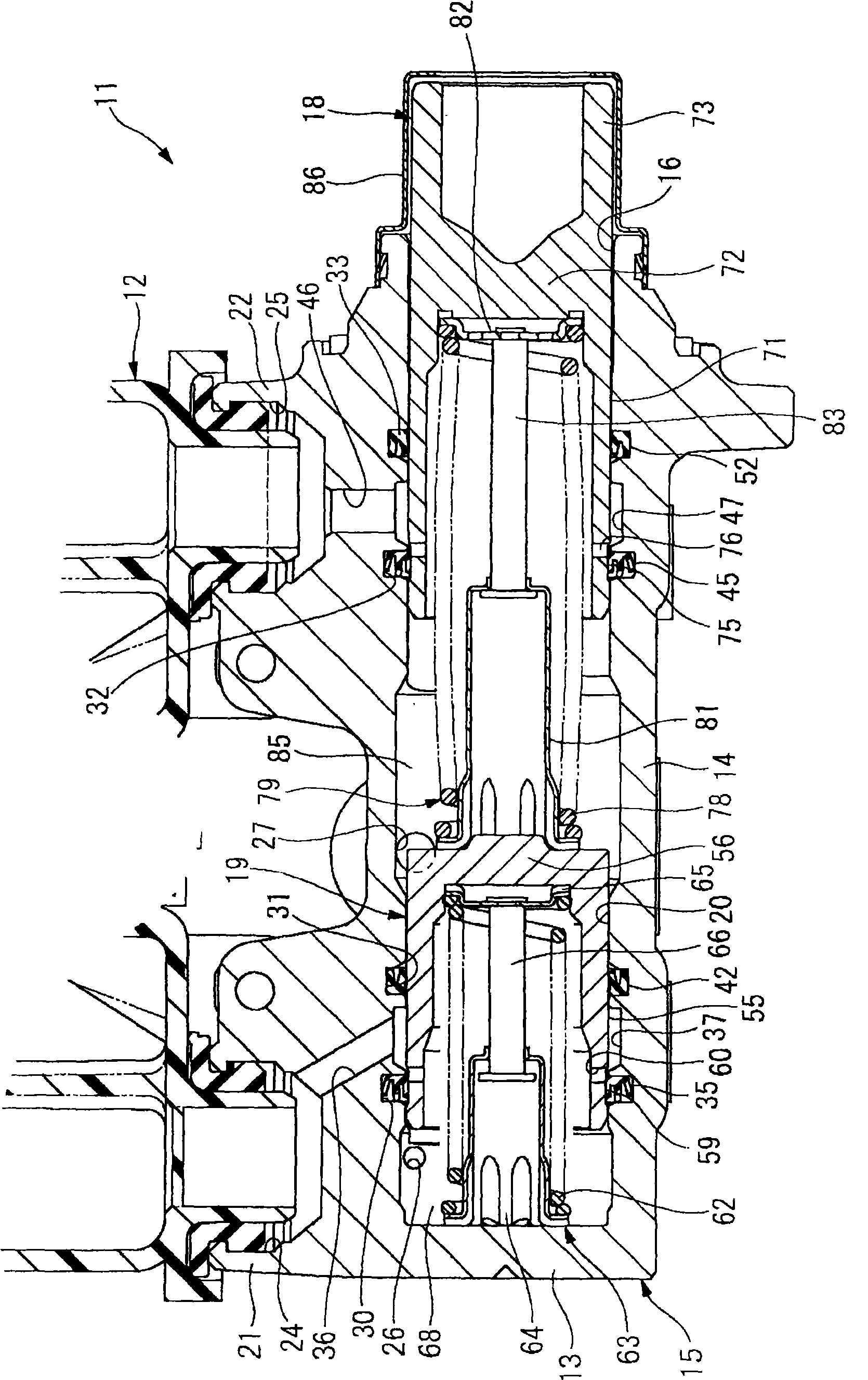
[0031] figure 1 Reference numeral 11 in the figure represents the master cylinder of this embodiment that generates the brake hydraulic pressure by using the force corresponding to the amount of brake pedal operation introduced through the brake booster not shown in the figure. The master cylinder 11 is equipped with a The fluid storage tank 12 for draining the brake fluid.

[0032] The master cylinder 11 is in series, and has: a cylinder body 15, which is processed from one material into a bottomed cylindrical shape with a bottom 13 and a cylindrical portion 14, and is arranged on the vehicle in a transverse posture; a primary piston 18, which can is slidably inserted into the opening 16 side of the cylinder body 15 ; The primary piston 18 and the secondary piston 19 are slidably guided along a sliding inner diameter portion 20 having a...

no. 2 example

[0062] Refer to the following side Figure 7 ~ Figure 10 A master cylinder according to a second embodiment of the present invention will be described centering on differences from the first embodiment. The parts that are the same as those in the first embodiment are given the same names and the same symbols, and their descriptions are omitted.

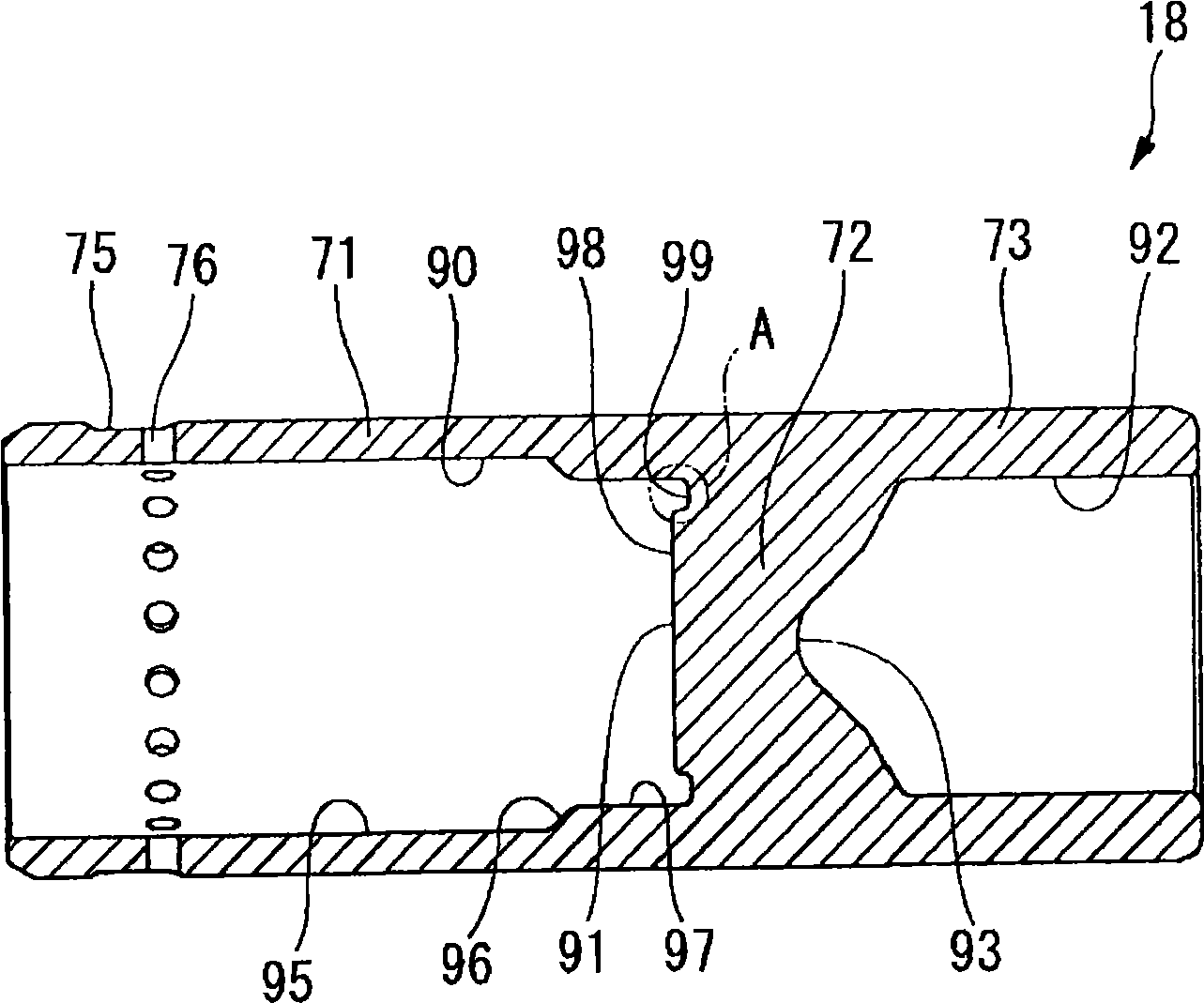
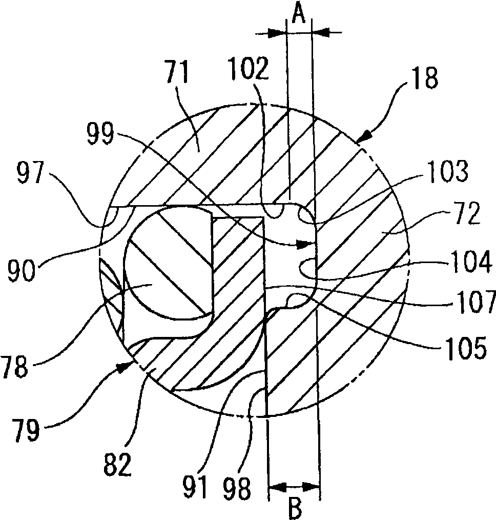
[0063] Such as Figure 7 As shown, the shape of a part of the primary piston 18 and the spring assembly 79 pressing it in the second embodiment are different from those of the first embodiment.

[0064] In the spring assembly 79 of the second embodiment, the partially provided end retainer 120 accommodated in the inner cylindrical portion 71 of the first-stage piston 18 is, for example, Figure 8 As shown, it includes: a flat disc portion 123, a joint hole 121 penetrating the axial direction is formed in the center, and peripheral holes 122 penetrating the axial direction are formed at many places (four places) around the joint hole...

no. 3 example 1

[0076] The following side mainly refers to Figure 11 to Figure 14 A master cylinder according to a third embodiment of the present invention will be described focusing on differences from the first embodiment. The parts that are the same as those in the first embodiment are given the same names and the same symbols, and their descriptions are omitted.

[0077] Such as Figure 11 As shown, the shape of a part of the primary piston 18 and the spring assembly 79 pressing it in the third embodiment are different from those in the first embodiment.

[0078] The spring assembly 79 of the third embodiment includes: a retainer 131 with a short axial length abutting against the bottom 56 of the secondary piston 19 , a retainer 132 with a long axial length abutting against the bottom 72 of the primary piston 18 , One end portion is fixed to the short holder 131 and supports the shaft member 133 slidably within a predetermined range by the long holder 132 . Thus, in the spring assemb...


PUM


Abstract

The invention provides a master cylinder capable of preventing a retainer from interfering with the maintainer inner bottom even a piston is formed by forging and capable of assuring excellent slide performance of the piston. The master cylinder comprises a bottomed cylindrical cylinder body, a piston (18) formed into a bottomed cylindrical shape and slidably disposed in the cylinder body, and a spring assembly (79) comprising a spring (78) urging the piston (18) toward an opening side of the cylinder body and a length of a spring of the spring assembly is determined by a retainer (82) which can abut against an inner bottom portion (91) of the piston (18). An annular groove (99) is formed on the most outer side of the inner bottom portion (91) of the piston (18)by the forging method.

Description

technical field [0001] The present invention relates to master cylinders. Background technique [0002] Existing technology disclosed as follows (for example, refer to patent document 1): for example, what the master cylinder used by automobile braking device has includes: a bottomed cylindrical cylinder body, a piston that slides in the cylinder body, and a piston that moves the piston to the cylinder body. The spring assembly that exerts force on the opening side makes the piston have a bottomed cylindrical shape and configures the spring assembly in its inner hole. And the bottomed cylindrical piston inner hole is formed by forging. [0003] Patent Document 1: JP-A-2002-104164 [0004] When the inner hole of the piston is formed by forging as described above, the butt joint between the axial wall portion of the inner hole and the bottom surface forms an arc-shaped wall surface connected in an arc shape. In this regard, the spring assembly inserted into the piston, for ...

Claims


Application Information

Patent Timeline
Patent Type & Authority Applications(China)
IPC IPC(8): B60T11/20
Inventor 荻原贵人木下岳之
Owner HITACHI LTD
Why Eureka
Try Eureka