Yarn end retrieving apparatus

A technology for a spinning device and a bobbin, which is applied in the field of spinning devices, can solve problems such as poor operation and inability to correctly capture the yarn end, and achieve the effect of simple production change.

Inactive Publication Date: 2009-09-30
MURATA MASCH LTD
View PDF2 Cites 16 Cited by
  • Summary
  • Abstract
  • Description
  • Claims
  • Application Information

AI Technical Summary

Problems solved by technology

In this way, if the length of the thread inserted into the core is longer or shorter, the yarn end cannot be correctly

Method used


Image

  • Yarn end retrieving apparatus
  • Yarn end retrieving apparatus
  • Yarn end retrieving apparatus

Examples


Embodiment Construction

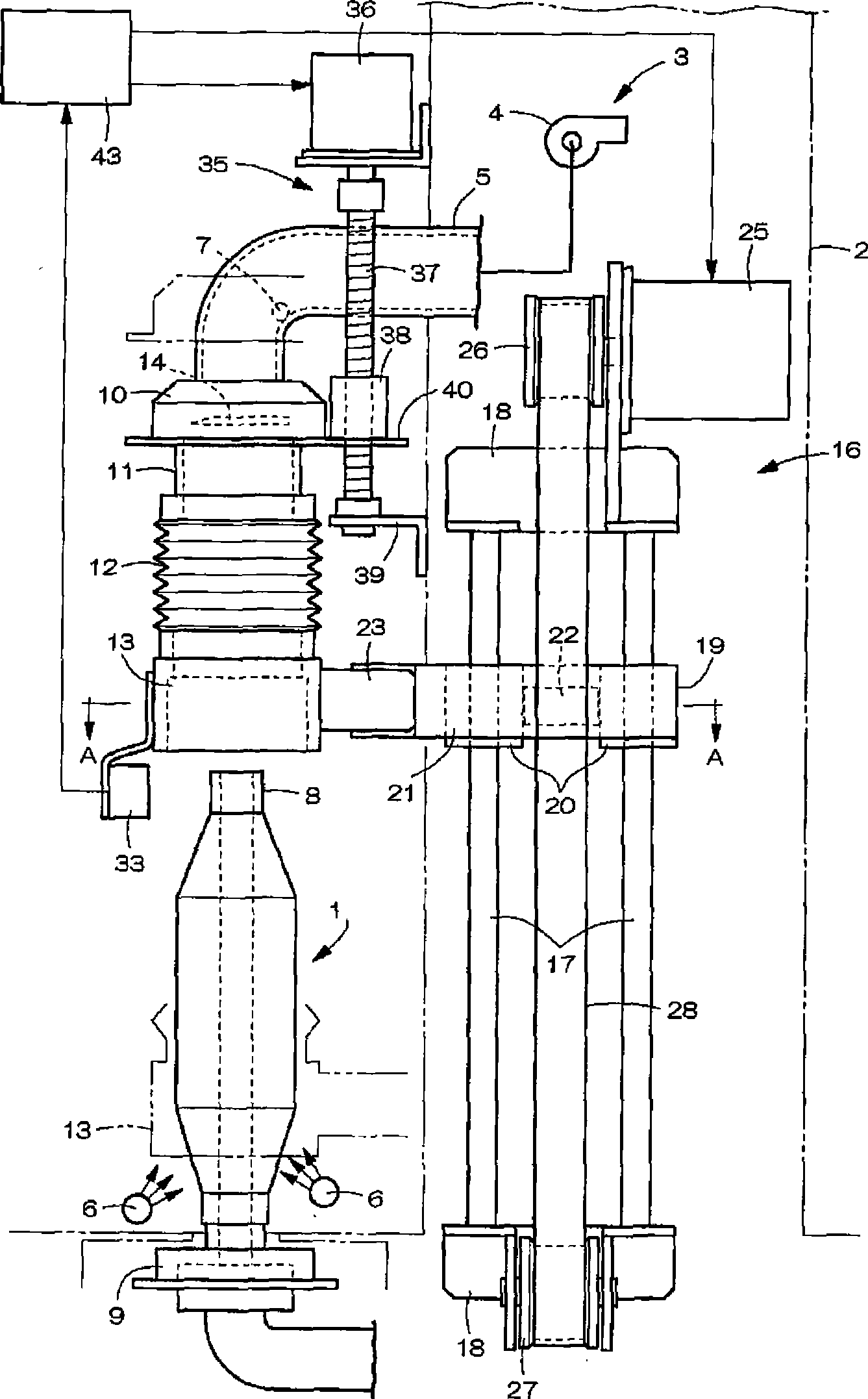
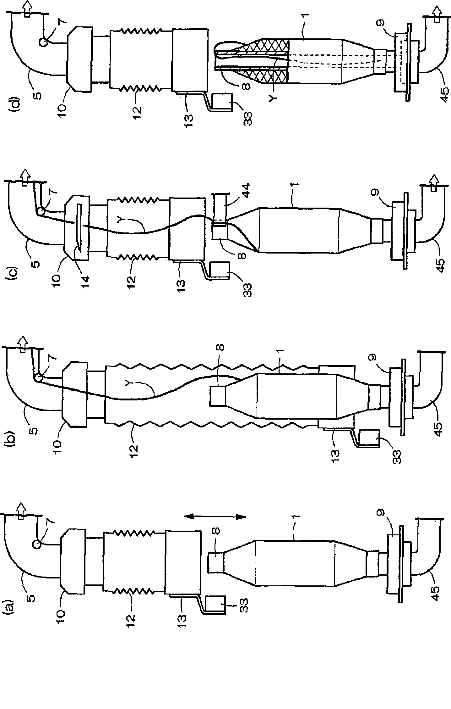
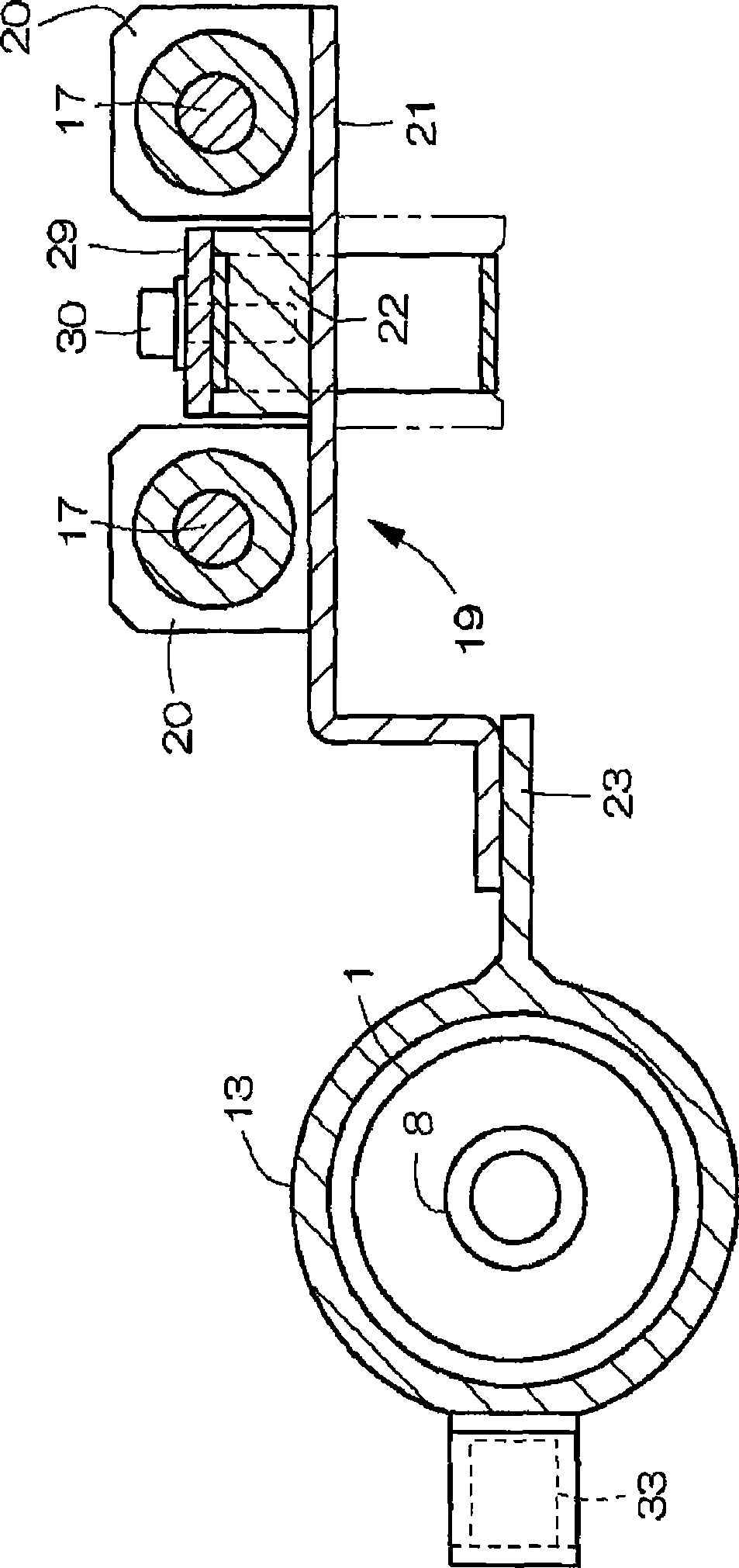
[0023] Figure 1 to Figure 3 An example of the spin-in device according to the present invention is shown. exist figure 1 Among them, the spin-in device has a vertically elongated body 2 arranged opposite to the conveying path of the bobbin 1, and a yarn detaching device 3 is arranged from the front upper part of the body 2 to the inside of the body. The yarn detaching device 3 is composed of a fan 4 for generating a suction air flow, a suction pipe 5 connected to the suction port of the fan 4, a pair of nozzles 6 for blowing compressed air toward the bobbin 1, and the like. The suction pipe 5 disposed on the front upper portion of the machine body 2 can be bent into an inverted L-shape, and the yarn detection sensor 7 is disposed at an inner corner of the bent portion. The bobbin 1 has a winding core 8 with upper and lower ends open, and the lower end of the winding core 8 is supported by a transport tray 9 provided along the transport path.

[0024] At the lower end of th...


PUM


Abstract

The invention provides a yarn end retrieving apparatus includes a yarn releasing device (3) that sucks and releases a yarn end from a surface of a bobbin (1), a cutter device (10) that cuts the yarn (Y) sucked out by the yarn releasing device (3), and a cylinder elevating and lowering device (16) that elevates and lowers a suction cylinder (13). The cylinder elevating and lowering device (16) is composed of a guide member (17), a slider (19) that slidably elevates and lowers along the guide member, and a driving structure that uses a stepping motor (25) as a driving source. The suction cylinder (13) is fixed to the slider (19) so as to be movable together with the slider. Power of the stepping motor (25) is used to elevate and lower the suction cylinder (13).

Description

technical field [0001] The present invention relates to a spin-in device that separates a yarn end from the surface of a bobbin (spinning bobbin), cuts the detached yarn to a certain length, and sucks it into a winding core of the bobbin. Background technique [0002] Such a spin-in device is known in Japanese Patent Application Laid-Open No. 7-97142. Then, the entire surface of the bobbin is covered with the suction cylinder, and the yarn end on the surface of the bobbin is sucked out by the suction airflow acting on the suction cylinder. The suction cylinder is guided and supported freely by the guide structure provided on the threading device. By operating the cylinder, the suction cylinder can be operated up and down between the standby position above the bobbin and the lowered position covering the entire surface of the bobbin. [0003] The suction cylinder is suspended by the cutter device via the vertically expandable elastic cylinder, so that the yarn sucked out thr...

Claims


Application Information

Patent Timeline
IPC IPC(8): B65H67/08
CPCB65H2701/31B65H67/088
Inventor 中川隆
Owner MURATA MASCH LTD
Why Eureka
Try Eureka