Damper of furniture

A damper and furniture technology, which is applied in the field of furniture dampers, can solve the problems of reduced service life, easy breakage at the end, small area, etc., and achieve the effects of reducing installation steps, avoiding cracking, and long life

Active Publication Date: 2009-09-30
伍志勇
View PDF2 Cites 7 Cited by
  • Summary
  • Abstract
  • Description
  • Claims
  • Application Information

AI Technical Summary

Problems solved by technology

In this structure, the end connecting the piston rod and the piston is narrow. When the piston rod is impacted, the end is easily broken. At the same time, due to the small area connected to the piston, it is easy to loosen, which greatly reduces the service life.

Method used


Image

  • Damper of furniture
  • Damper of furniture
  • Damper of furniture

Examples


Embodiment Construction

[0022] The present invention will be further described below in conjunction with the accompanying drawings and embodiments.

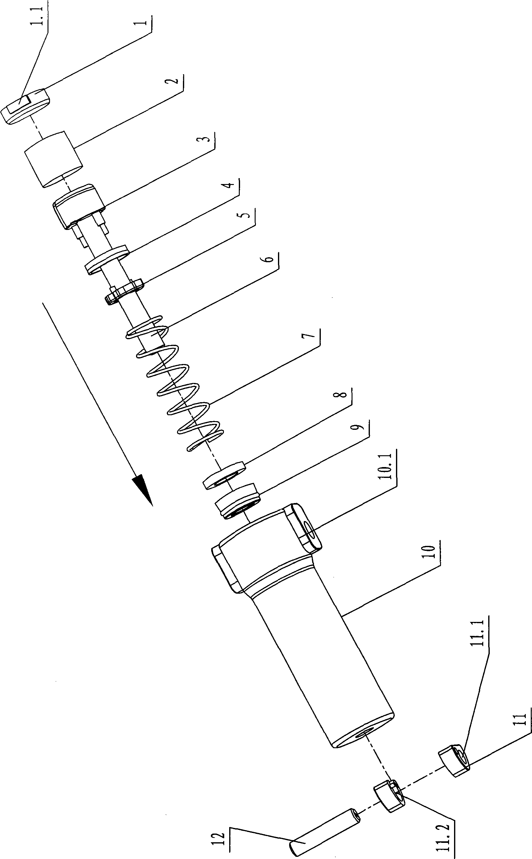
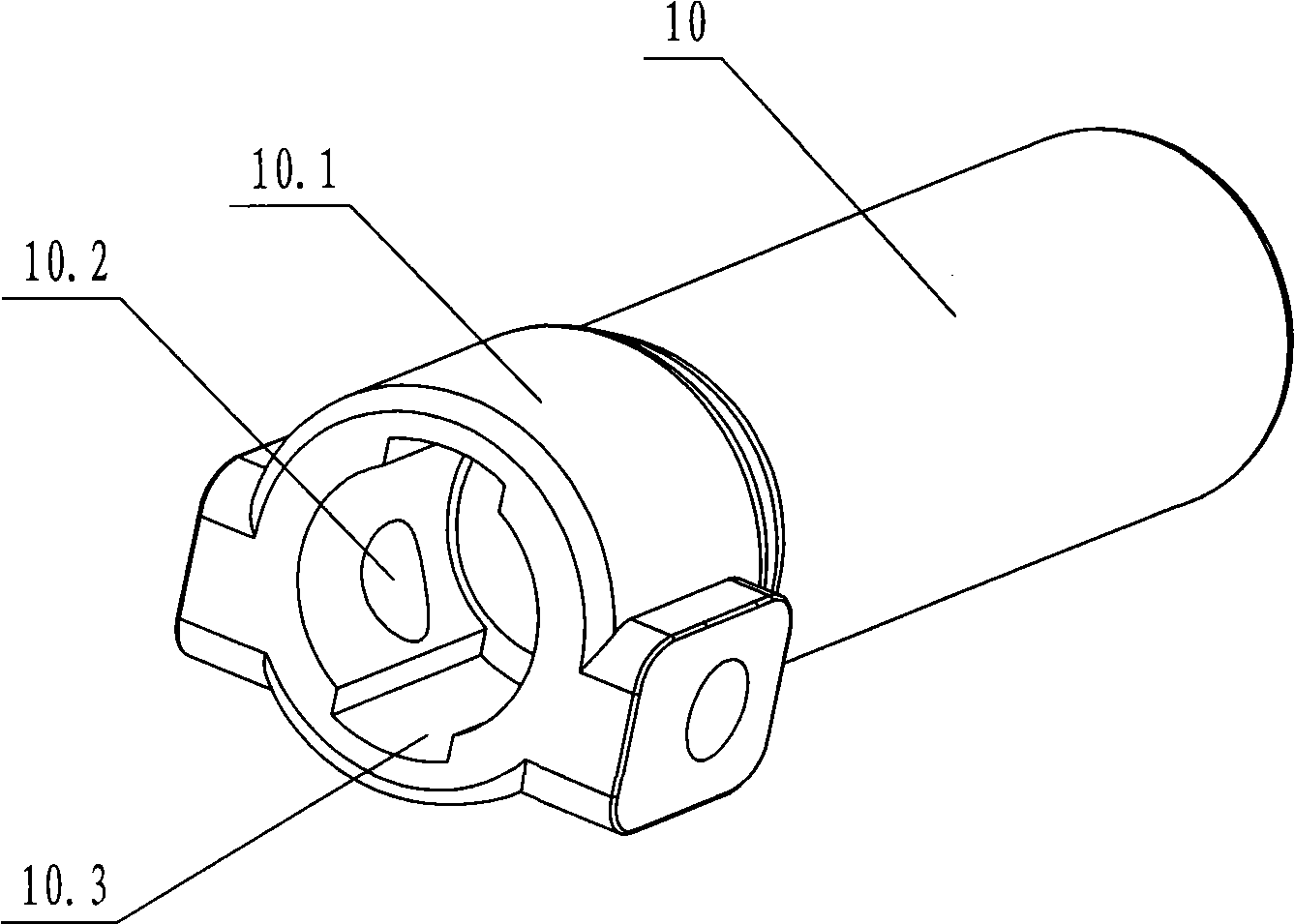
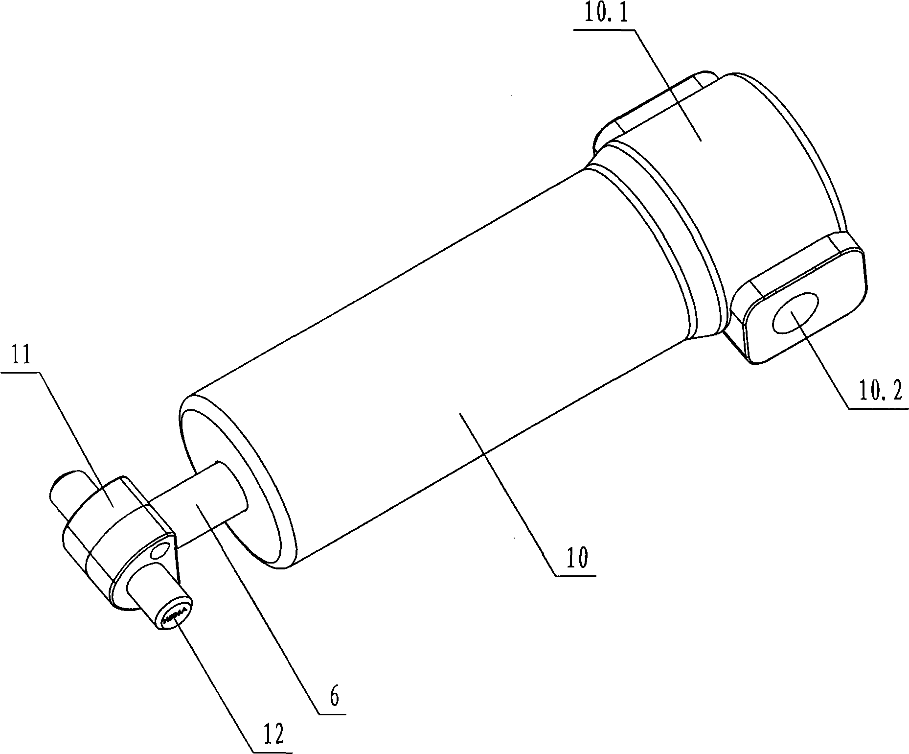
[0023] see Figure 1-Figure 8 , the damper of this furniture includes hinge fixing seat 13, hinge arm 15 and rocker arm 14, one end of the damper is connected with the hinge arm, and the other end is connected with the rocker arm, see Figure 8 . The damper includes a piston 3, a damping plate 4 and a limiting plate 5 arranged in the cylinder body 10, and one end of the piston rod 6 extends into the cylinder body, passes through the limiting plate and the damping plate, and connects with the piston. There is one or more first overflow grooves 3.1 on the outside of the piston, and an annular step 4.1 is provided on the side of the damping plate facing the limit plate, and a certain oil clearance gap is maintained between the piston, damping plate, limit plate and the inner wall of the cylinder ,See Figure 7 . The front end of the cylinder body 10 is...


PUM


Abstract

A damper of furniture comprises a piston and a damp plate which are sequentially connected in a cylinder. One end of a piston rod extends into the cylinder and is connected with the piston after penetrating through the damp plate; the piston is provided with more than one flow-passing hole, or the outer side of the piston is provided with more than one first flow-passing groove; one side of the damp plate, opposite to the piston, is provided with an annular step; a certain oil-passing gap is retained between the piston and the inner wall of the cylinder and between the damp plate and the inner wall of the cylinder; one end of the piston rod, connected with the piston, is in a T shape and is connected with the piston as a whole. The damper can be arranged in a pivoted arm, rotates flexibly and can not easily loose. When a door is closed, the damper has strong impact resistance, can effectively slow down the closing speed and reduce the collision sound generated by closing the door, andthe door is opened without any influence. The invention has simple and reasonable structure, low manufacture cost and long service life.

Description

technical field [0001] The invention relates to a damper for furniture, which is mainly used on hinges and slide rails. Background technique [0002] Chinese Patent Document No. CN2802015Y discloses a hinge for furniture, including a hinge arm and a hinge cup. The hinge arm is provided with a base, and an outer hinge and an inner hinge are arranged between the hinge cup. The parts are respectively hinged with the upper installation shaft and the lower installation shaft of the hinge arm. A spring is arranged on the upper installation shaft. One end of the spring is pressed against the outer wall of the outer hinge, and the other end is pressed against the fixed shaft of the hinge arm. There is a cavity on the base. A buffer device is provided in the cavity. The buffer device includes a cylinder body sealed at both ends, a piston rod set in the cylinder body and a piston fixed on the piston rod. There is an outer sealing groove on the outer surface of the piston, and damping...

Claims


Application Information

Patent Timeline
Patent Type & Authority Applications(China)
IPC IPC(8): E05D7/086E05F1/10E05F3/20E05F5/10
Inventor 伍志勇
Owner 伍志勇
Why Eureka
Try Eureka