Sealing means between rotor and housing in a water turbine

A water turbine and rotor technology, applied in engine sealing, mechanical equipment, hydroelectric power generation, etc., can solve problems such as loss, large gap, loss sealing, etc., and achieve the effect of improving efficiency

Inactive Publication Date: 2012-07-11
ANDRITZ TECH & ASSET MANAGEMENT
View PDF6 Cites 0 Cited by
  • Summary
  • Abstract
  • Description
  • Claims
  • Application Information

AI Technical Summary

Problems solved by technology

[0002] In this type of turbine, the problem is that most of the losses are related to seal leakage
Simple labyrinth seals are commonly used today, but they require large gaps and thus have large losses

Method used


Image

  • Sealing means between rotor and housing in a water turbine
  • Sealing means between rotor and housing in a water turbine

Examples


Embodiment Construction

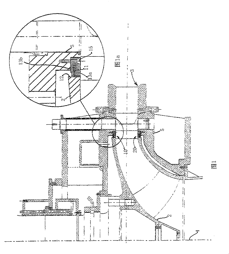
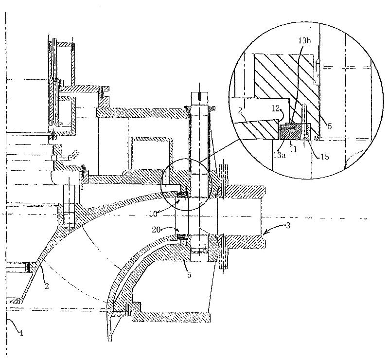
[0018] As is conventional, the shown turbomachine comprises a rotor 2 with an axis of rotation 1 , which in this example is vertical, ie perpendicular to the axis of rotation 1 . A housing structure 5 surrounds the rotor and includes guide vane ducts 5 for directing water towards the rotor 2 . This water should be prevented as much as possible from escaping in the gap between the housing part of the rotor and the immediately adjacent part. For this purpose, seals as indicated at 10 and 20 are provided.

[0019] Seal 10 in Figure 1a shown in more detail. The seal 20 has a corresponding design. Therefore, in Figure 1a In the rotor 2 and adjacent parts of the housing 5 are shaped to accommodate a seal 10 in the form of a brush seal, the main component of which is essentially a brush or bristle assembly 11 . It is mounted between the clip members 13a and 13b so that the protruding bristle ends abut against the radially outward outer end face 12 at the circumference of the r...


PUM


Abstract

The present invention discloses a water turbine of the reaction type, such as a Francis or Kaplan turbine, comprising a rotor (2) and a surrounding housing (5), with sealing means (10,20) between the rotor and the housing. The sealing means comprises brush seals (11,12,13a,b) located at a radial distance from the vertical rotor axis (1) being a major proportion of the maximum radial dimension of the rotor(2).

Description

technical field [0001] The present invention relates to a reaction water turbine, such as a Francis or axial flow turbine, comprising a rotor and a surrounding casing with sealing means between said rotor and said casing. Background technique [0002] In this type of turbine, there is a problem that most of the losses are related to seal leakage. Simple labyrinth seals are commonly used today, but they require large gaps and therefore have large losses. The dimensions of the structures involved should be taken into account in this respect; conventional shaft seals are not the focus of this article. [0003] US Patent 4,464,580 (Miller) is an example of a conventional water turbine with seals provided at locations corresponding to the concerns of the present invention, ie at appropriate radial distances from the rotor shaft. These known seals are lip seals. [0004] US Patent 4,293,777 (Gamell) relates to a very specific type of turbine ("drag turbine") provided with brush...

Claims


Application Information

Patent Timeline
Patent Type & Authority Patents(China)
IPC IPC(8): F03B11/00F01D5/20F16J15/32
CPCF16J15/3288Y02E10/226F03B11/006F05B2240/571F16J15/3456F03B3/02Y02E10/20
Inventor 阿兰·德默斯安德斯·韦德马克
Owner ANDRITZ TECH & ASSET MANAGEMENT
Why Eureka
Try Eureka