
Turbine cooling cascade with vortex structure

A turbine cooling and trapped vortex technology, applied in the combustion method, combustion chamber, combustion equipment, etc., can solve the problems of easy burnout of the leading edge end wall of the blade, affecting the performance of the blade cascade, and significant heat transfer characteristics, reducing cold air. The effect of utilization, reduction of mixing loss, and improvement of air-conditioning utilization rate

Inactive Publication Date: 2009-10-07
HARBIN INST OF TECH
View PDF0 Cites 10 Cited by
  • Summary
  • Abstract
  • Description
  • Claims
  • Application Information

AI Technical Summary

Problems solved by technology

[0005] The purpose of the present invention is to solve the problem of flow loss and mixing loss caused by the existence of the horseshoe vortex structure in the existing cascade, which affects the performance of the cascade, and the heat transfer characteristics near the end wall of the blade and the surface of the blade are significant, and the front of the blade The problem that the wall surface of the edge and the leading edge end wall of the blade is extremely easy to burn out, and then a turbine cooling blade cascade with a vortex structure is provided.

Method used


Image

  • Turbine cooling cascade with vortex structure
  • Turbine cooling cascade with vortex structure
  • Turbine cooling cascade with vortex structure

Examples


specific Embodiment approach 1

[0009] Embodiment 1: Combining Figure 4 ~ Figure 7 Describing this embodiment, the turbine cooling cascade with trapped vortex structure of this embodiment includes a wall 1 and a blade 2, the blade 2 is arranged on the wall 1, and the blade 2 is close to the pressure surface of the blade leading edge 2-1 2-2, the suction surface 2-3 of the blade 2 close to the leading edge of the blade 2-1, and the end wall 1-1 of the blade leading edge of the wall 1 are provided with a plurality of long grooves 3 arranged in rows, and the blade 2 Each long groove 3 on the pressure surface 2-2 close to the blade leading edge 2-1 and each long groove 3 on the suction surface 2-3 of the blade 2 close to the blade leading edge 2-1 are along the height direction of the blade 2 Open, each long groove 3 on the blade leading edge end wall 1-1 of the wall 1 is opened along the width direction of the wall 1, and one side wall of each long groove 3 is opened along the length direction of the long groo...

specific Embodiment approach 2

[0010] Specific implementation mode 2: Combining Figure 4 ~ Figure 7 Illustrating this embodiment, in this embodiment, the pressure surface 2-2 of the blade 2 close to the trailing edge 2-4 of the blade and the suction surface 2-3 of the blade 2 close to the trailing edge 2-4 of the blade are both opened in rows. Each long groove 3 on the pressure surface 2-2 of the blade 2 close to the trailing edge 2-4 of the blade and each long groove 3 on the suction surface 2-3 of the blade 2 close to the trailing edge 2-4 of the blade All are opened along the height direction of the blade 2 . This arrangement effectively avoids the burnout of the pressure surface, the suction surface and the high temperature area of ​​the trailing edge, and effectively improves the overall performance of the blade. Other components and connection relationships are the same as in the first embodiment.

specific Embodiment approach 3

[0011] Specific implementation three: combination Figure 4 ~ Figure 7 Illustrating this embodiment, the cross section of the long groove 3 in this embodiment is a square, a trapezoid or a semicircle. In this way, the blade as a whole has diversity, and the strength of the standing vortex and the covering effect of the thin-layered gas film are better. Other compositions and connection relationships are the same as in the second embodiment.


PUM


Abstract

A turbine cooling cascade with a vortex structure relates to a turbine cooling cascade. The invention settles the problems of flowing loss, blending loss and easy burning of blade leading edge and end wall surface of blade leading edge caused by the existence of horse shoe vortex structure in the prior blade cascade. According to the blade (2) of the invention, a pressure surface (2-2) next to the blade leading edge (2-1), a suction surface (2-3) of blade (2) next to the blade leading edge (2-1) and the blade leading edge (1-1) of wall (1) are respectively provided with a plurality of elongated slots (3) which are distributed in row. One side wall of each elongated slot (3) is provided with a plurality of cold air injection openings (4). Furthermore the positions of cold air injection opening (4) are next to the base of elongated slot (3). The turbine cooling cascade with vortex structure according to the invention reduces the flowing loss at the inner part of flow passage, reduces the bigger blending loss of air currents with different flowing velocities, provides better thermal protection function for the end wall of blade and the blade surface, effectively protects the end wall adjacent with the blade leading edge and the high-temperature area on the surface of blade, and increases the usage factor of cold air.

Description

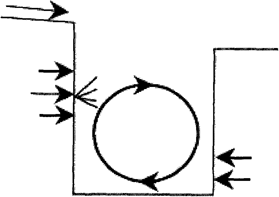
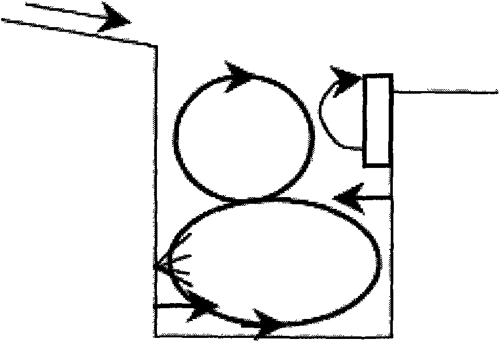
technical field [0001] The invention relates to a turbine cooling blade cascade. Background technique [0002] Natural standing vortices can be seen on the sheltered sides of exposed ridges in nature, and similar standing vortices can be seen near sand dunes. When the fluid flows through a cavity, a trapped vortex will also be generated in the cavity due to the viscous effect. For different air blowing positions before and after the cavity, two different structures of double vortex and single vortex can be formed (such as figure 1 and figure 2 shown), the large vortex at the bottom of the double vortex structure is also called the primary vortex, and the small vortex above is also called the secondary vortex. The characteristic of the double vortex structure is that the large vortex at the bottom of the cavity is very stable, and the secondary vortex at the upper part of the cavity can make the gas in the trapped vortex mix with the mainstream air better and faster. [...

Claims


Application Information

Patent Timeline
Patent Type & Authority Applications(China)
IPC IPC(8): F23R3/14F23R3/58
Inventor 黄洪雁王振峰王松涛周逊韩万金
Owner HARBIN INST OF TECH
Learn More