Turbine cooling cascade with vortex structure
A turbine cooling and trapped vortex technology, which is applied in the combustion method, combustion chamber, combustion equipment, etc., can solve the problems of easy burnout of the leading edge end wall of the blade, affecting the performance of the blade cascade, and significant heat transfer characteristics, reducing the amount of cold air. The effect of utilization, reduction of mixing loss, and improvement of air-conditioning utilization rate
- Summary
- Abstract
- Description
- Claims
- Application Information
AI Technical Summary
Problems solved by technology
Method used
Image
Examples
specific Embodiment approach 1
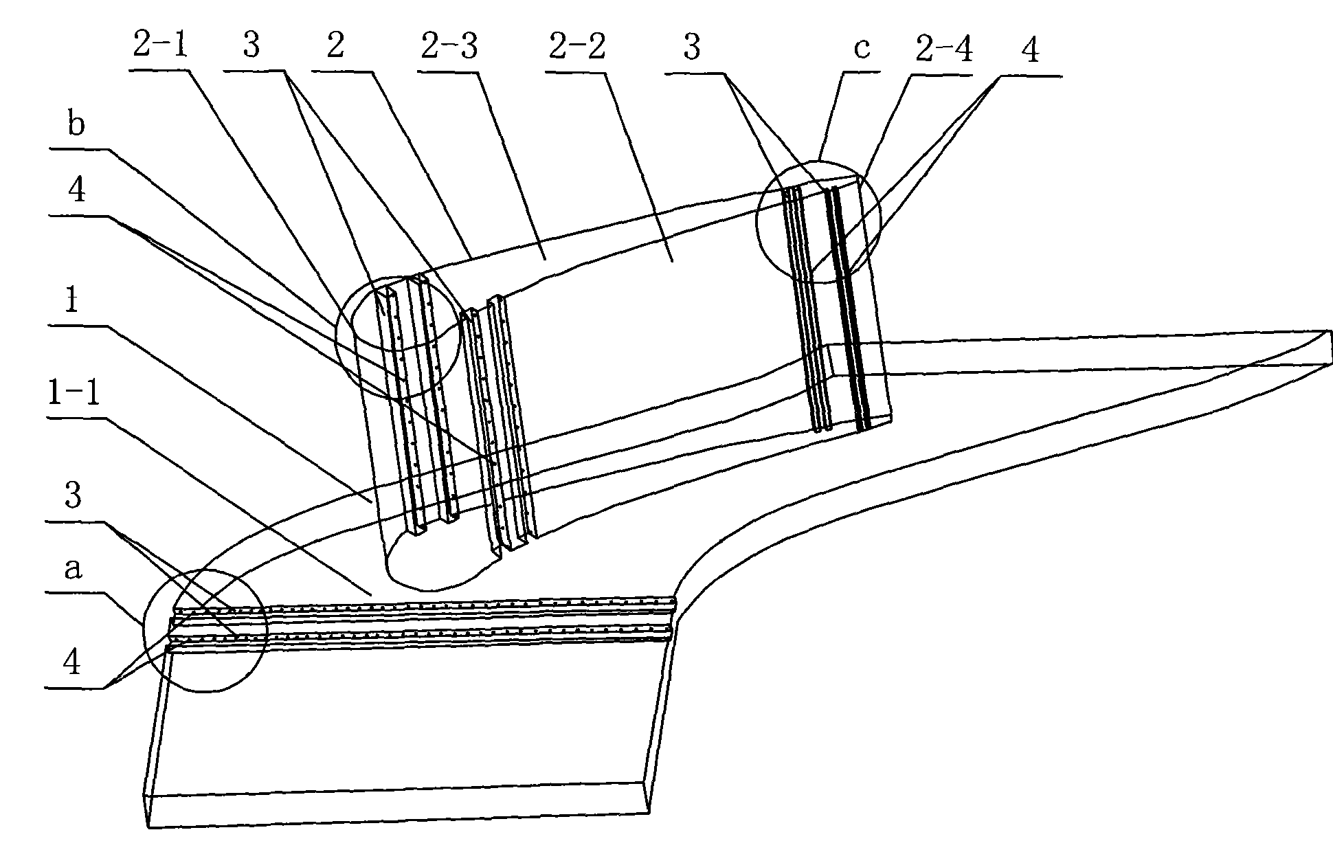
[0009] Specific Embodiment 1: This embodiment is described with reference to FIGS. 4 to 7. The turbine cooling cascade with a vortex structure in this embodiment includes a wall 1 and blades 2. The blades 2 are arranged on the wall 1. The blades 2 On the pressure surface 2-2 close to the blade leading edge 2-1, on the suction surface 2-3 of the blade 2 close to the blade leading edge 2-1, and on the blade leading edge end wall 1-1 of the wall 1, there are rows of A plurality of long grooves 3 arranged, each long groove 3 on the pressure surface 2-2 of the blade 2 close to the blade leading edge 2-1 and each long groove 3 on the suction surface 2-3 of the blade 2 close to the blade leading edge 2-1 Each long groove 3 is opened along the height direction of the blade 2, and each long groove 3 on the blade leading edge end wall 1-1 of the wall 1 is all opened along the width direction of the wall 1, and one side of each long groove 3 A plurality of cold air injection holes 4 are ...
specific Embodiment approach 2
[0010] Specific Embodiment 2: This embodiment is described in conjunction with FIGS. 4 to 7. In this embodiment, the pressure surface 2-2 of the blade 2 close to the blade trailing edge 2-4 and the suction surface 2- of the blade 2 close to the blade trailing edge 2-4 3 are provided with a plurality of long grooves 3 arranged in a row, each long groove 3 on the pressure surface 2-2 of the blade 2 close to the blade trailing edge 2-4 and the suction force of the blade 2 close to the blade trailing edge 2-4 Each long groove 3 on the surface 2-3 is opened along the height direction of the blade 2. Such setting can effectively avoid burning out of the pressure surface, suction surface and high-temperature area of the trailing edge, and effectively improve the overall performance of the blade. Other compositions and connections are the same as in the first embodiment.
specific Embodiment approach 3
[0011] Specific Embodiment 3: This embodiment is described with reference to FIGS. 4 to 7 . The cross section of the long groove 3 in this embodiment is square, trapezoidal or semicircular. With such a setting, the overall blade has diversity, and the coverage effect of the strength of the standing vortex and the thin layered air film is better. Other compositions and connections are the same as those in the second embodiment.
PUM
 Abstract
Description
Claims
Application Information
 - R&D
- Intellectual Property
- Life Sciences
- Materials
- Tech Scout
- Unparalleled Data Quality
- Higher Quality Content
- 60% Fewer Hallucinations
Browse by: Latest US Patents, China's latest patents, Technical Efficacy Thesaurus, Application Domain, Technology Topic, Popular Technical Reports.
© 2025 PatSnap. All rights reserved.Legal|Privacy policy|Modern Slavery Act Transparency Statement|Sitemap|About US| Contact US: help@patsnap.com


