Vertical belt middle sampling head
A sampling head and belt technology, applied in the field of sampling equipment, can solve the problems of representative deviation, residual material, large volume of the transmission mechanism, etc., and achieve the effect of complete sampling section, no residual material, and flexible installation position.
- Summary
- Abstract
- Description
- Claims
- Application Information
AI Technical Summary
Problems solved by technology
Method used
Image

Examples
Embodiment Construction
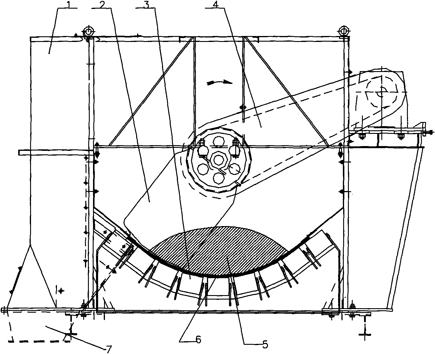
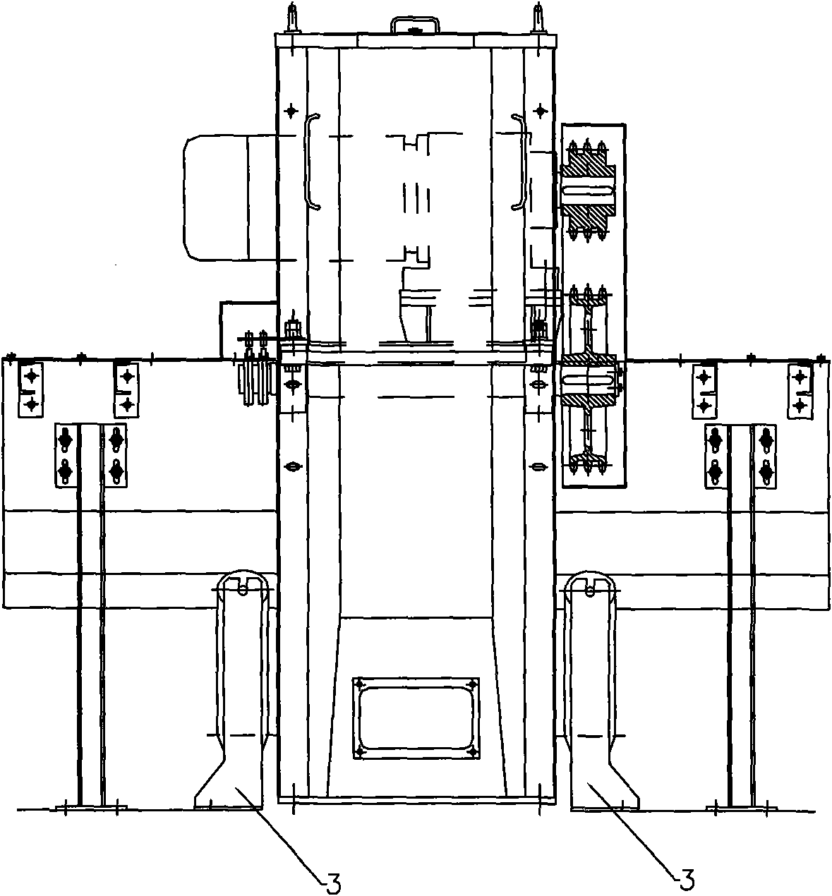
[0016] The specific embodiments of the present invention will be described below in conjunction with the accompanying drawings. Such as figure 1 , figure 2 As shown, the vertical belt middle sampling head of the present invention includes a multi-supporting roller support structure composed of a frame 1, a sampling bucket 2, and two sets of arc rollers 3.
[0017] Frame 1 is installed on an independent floor support, and is not affected by the belt conveyor support and intermediate frame.
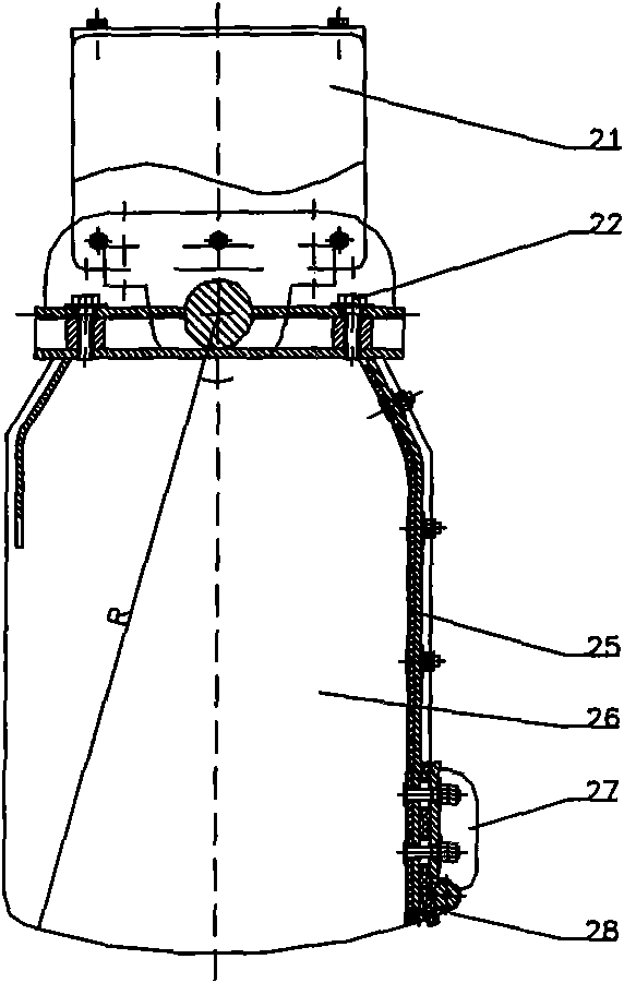
[0018] combine Figure 1 to Figure 4 , the sampling bucket body 26 is connected with the connection plate on the transmission shaft 23 through the connection bolt 22, and the transmission shaft is suspended at the middle position inside the frame 1 by an integral vertical bearing unit 24. The transmission reduction device 4 is installed on one side of the frame 1, and drives the sampling bucket 2 to rotate around the transmission shaft 23 through belt or chain transmission.
[0019] co...
PUM
 Abstract
Description
Claims
Application Information