LCD device

A liquid crystal display device and liquid crystal display panel technology, which are applied in nonlinear optics, instruments, optics, etc., can solve the problems of peeling off the liquid crystal display panel from the backlight module, affecting product quality and product life, and poor structural stability of the backlight module, etc. Achieve the effect of improving fixed reliability, improving complicated procedures, and saving consumption

Active Publication Date: 2009-10-07
AU OPTRONICS (SUZHOU) CORP LTD +2
View PDF7 Cites 6 Cited by
  • Summary
  • Abstract
  • Description
  • Claims
  • Application Information

AI Technical Summary

Problems solved by technology

For example, in an edge-lit backlight module, the light guide plate is directly placed on the reflector inside the plastic frame, and then fixed by the outer frame. In essence, there is no fixed structure between the light guide plate and the plastic frame. Depending on the size matching between the light guide plate and the plastic frame, if there is a slight deviation in the actual size after processing, there will be a problem of abnormal sound, and because the structural stability of the entire backlight module is relatively poor, it will seriously affect the product quality and product life.
For another example, in the direct type backlight module, the diffusion plate is fixed on the lamp tube fixing seat by double-sided adhesive tape. Although this fixing method can achieve a certain fixing effect, it is not easy to assemble and disassemble.
In addition, in order to prevent light leakage in the liquid crystal display device, it is necessary to paste light-shielding tape on the outer edge of the liquid crystal display panel, and the use of light-shielding tape will make heavy work difficult, and the liquid crystal display panel and the backlight module may also be peeled off due to insufficient adhesion.
[0005] Therefore, it is necessary to provide a new liquid crystal display device to overcome the defects in the prior art that cannot be fixed or inconvenient to assemble liquid crystal display panels and optical components

Method used


Image

  • LCD device
  • LCD device
  • LCD device

Examples


Embodiment Construction

[0016] The following descriptions of the various embodiments refer to the accompanying drawings to illustrate specific embodiments in which the present invention can be practiced. The directional terms mentioned in the present invention, such as "up", "down", "front", "back", "left", "right", "top", "bottom", "horizontal", "vertical" etc. are merely for reference to the directions of the attached drawings. Therefore, the used directional terms are only used to illustrate and understand the present invention, but not to limit the present invention.

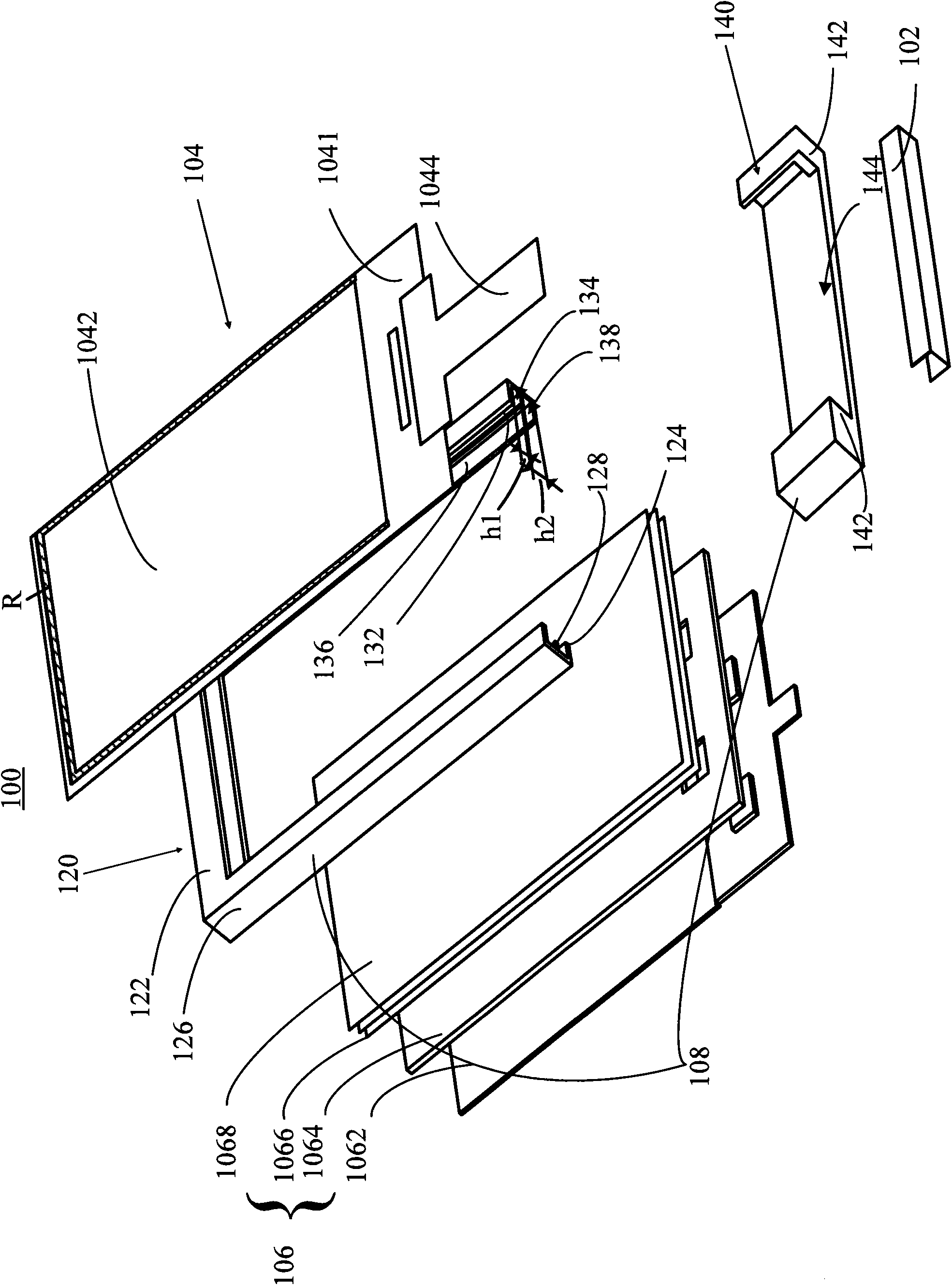
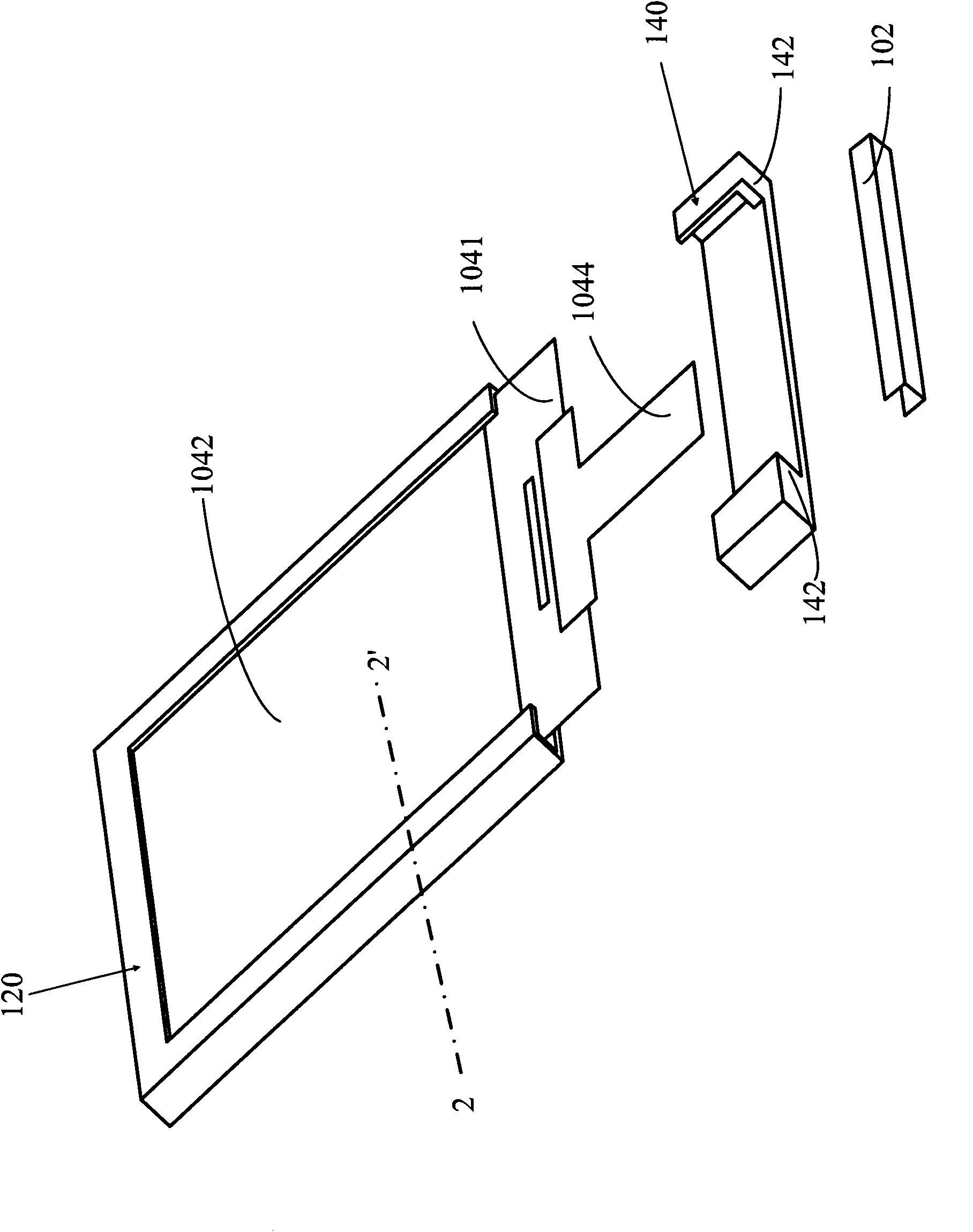
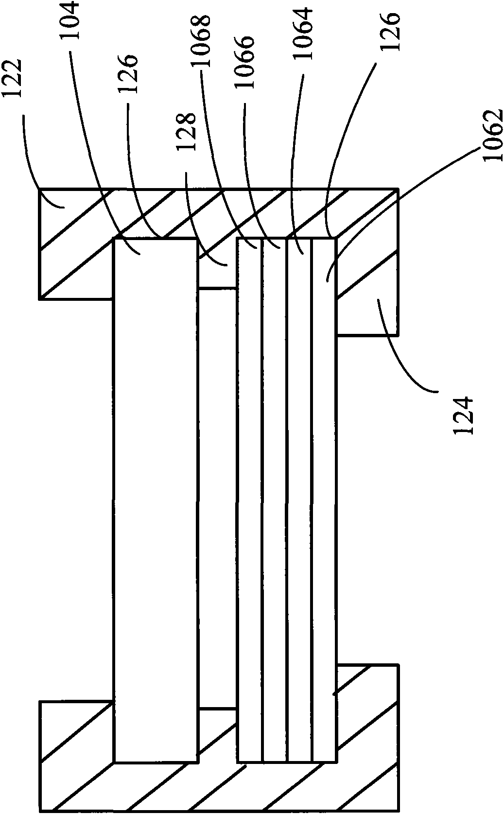
[0017] see figure 1 , figure 1 It is an exploded view of the first embodiment of the liquid crystal display device of the present invention. The liquid crystal display device 100 of the present invention includes a light source 102 , a liquid crystal display panel 104 , an optical film set 106 and a plastic frame 108 . The plastic frame 108 is used to fix the liquid crystal display panel 104 , the optical film set 106 and the l...


PUM


Abstract

The invention provides an LCD device, comprising a liquid crystal display panel, an optical film set and a plastic frame. The plastic frame comprises a first body and a second body, wherein the first body has a first frame body and a second frame body, and a spacing plate protruding from the side walls is fixed between the two frame bodies. Edges, the spacing plate and the side wall of the first frame body form a first guide groove and a first opening, and the liquid crystal display panel is inserted from the first opening and fixed in the first guide groove. Edges, the spacing plate and the side walls of the second frame body form a second guide groove and a second opening, and the optical film set is inserted from the second opening and fixed in the second guide groove. The first body the second body are connected and covers the first and the second openings, for fixing the liquid crystal display panel and the optical film set in the plastic frame.

Description

technical field [0001] The invention relates to a plane display, in particular to a liquid crystal display device with a plastic frame. Background technique [0002] Displays with advanced functions have gradually become an important feature of today's consumer electronics products, among which liquid crystal display devices have gradually become the mainstay of various electronic devices such as televisions, mobile phones, personal digital assistants (Personal Digital Assistant, PDA), digital cameras, computer screens or notebooks. Widely used on computer screens. The backlight module (Back Light Module) can provide a uniform and high-brightness light source for the liquid crystal display device panel, so that the liquid crystal display device panel can display images normally. [0003] Usually the backlight module is mainly composed of a light source, a reflector, a light guide plate, various optical films (such as a diffuser, a prism, etc.) and a plastic frame. The back...

Claims


Application Information

Patent Timeline
Patent Type & Authority Applications(China)
IPC IPC(8): G02F1/13
Inventor 李艳红朱燕辉田昕王兰娟
Owner AU OPTRONICS (SUZHOU) CORP LTD
Why Eureka
Try Eureka