Welder transformer and manufacturing method thereof

A transformer and welding machine technology, applied in the direction of inductance/transformer/magnet manufacturing, transformer/inductor core, transformer/inductor coil/winding/connection, etc., can solve the problem of low efficiency, low transformer efficiency, and transformer manufacturing Complex process and other issues, to achieve the effect of simplifying the assembly process, improving efficiency, and simplifying the docking process

Active Publication Date: 2009-10-07
ZHEJIANG KENDE MECHANICAL & ELECTRICAL
View PDF0 Cites 11 Cited by
  • Summary
  • Abstract
  • Description
  • Claims
  • Application Information

AI Technical Summary

Problems solved by technology

[0002] Transformer is an essential part of electrical equipment such as welding machines. At present, the process of making such a small or miniature transformer is relatively complicated. The usual processing steps are as follows: first process silicon steel sheets of specific specifications, and weigh the silicon steel sheets according to the size of the transformer. , and fasten the steel and silicon sheets into a transformer core; on the other hand, the coil is wound on the processed skeleton, and the skeleton is made into a primary winding and a secondary winding respectively; next, the primary winding and the secondary winding Put them into the above-mentioned manufactured iron cores respectively, then butt the primary and secondary iron cores and manually weld them into a whole, and then install other accessories. The whole manufacturing process of the transformer is more complicated and the efficiency is lower. Large-scale production cannot be realized; in addition, the current welding machine transformer is usually a structure in which the coil winding wraps the transformer core. Because the magnetic induction line is not completely closed, there is a certain magnetic flux leakage phenomenon, resulting in low transformer efficiency.

Method used


Image

  • Welder transformer and manufacturing method thereof
  • Welder transformer and manufacturing method thereof
  • Welder transformer and manufacturing method thereof

Examples


Embodiment Construction

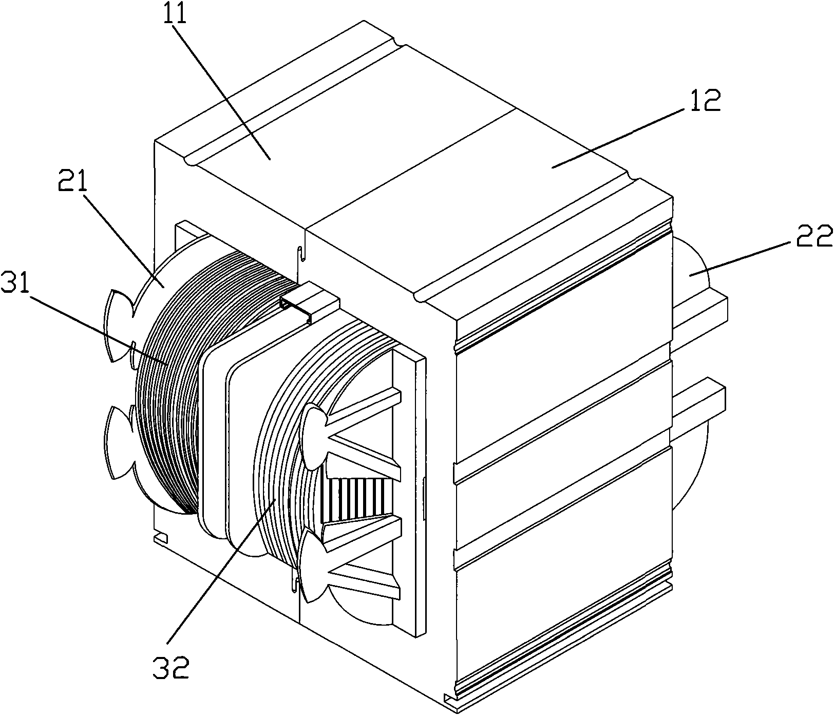
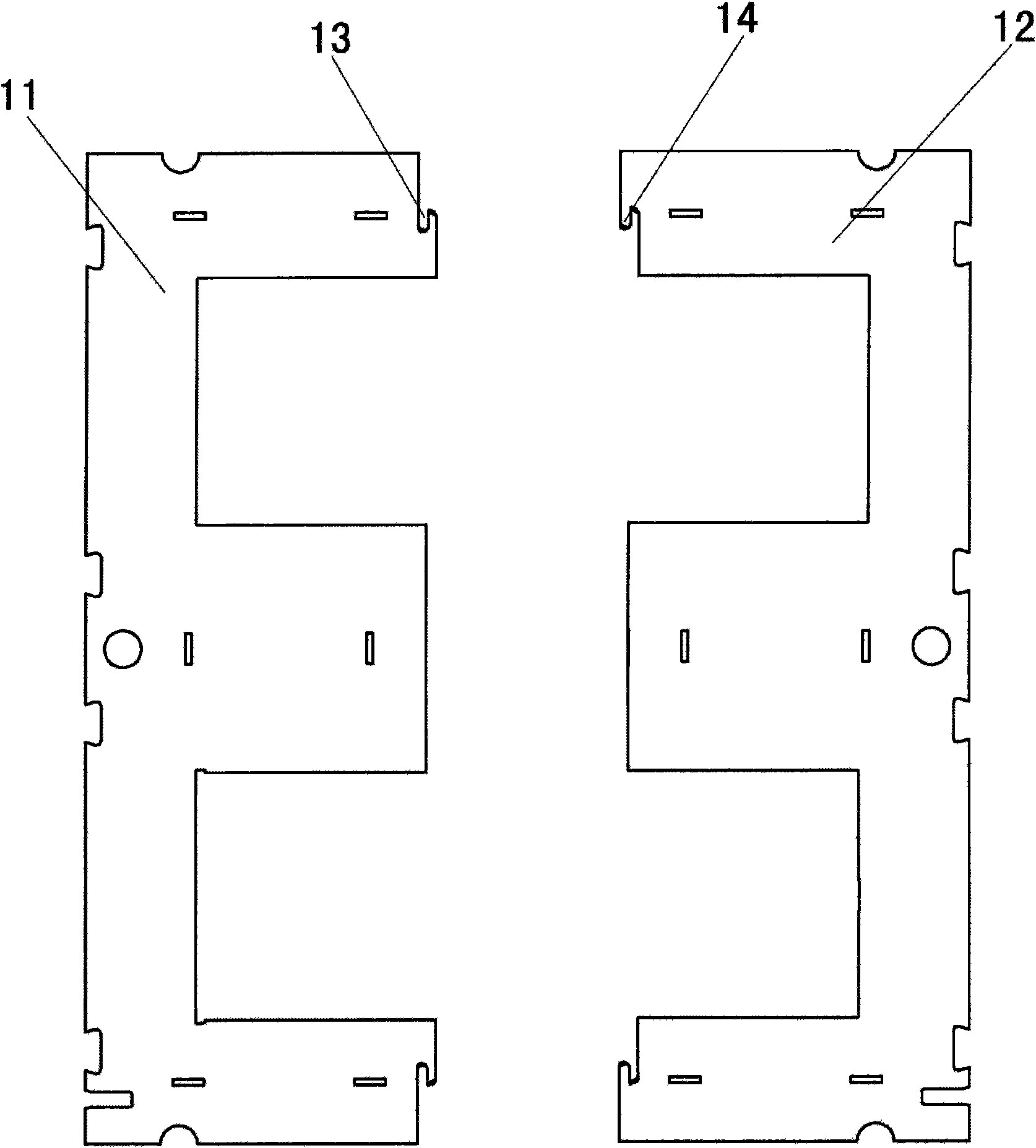
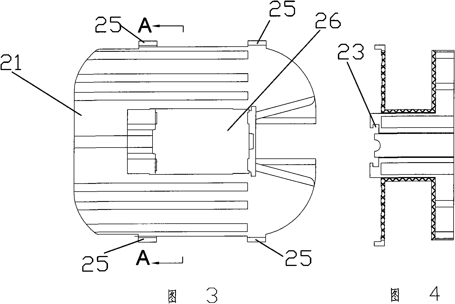
[0019] Such as Figure 1-9 As shown, a welding machine transformer includes a primary iron core 11, a secondary iron core 12, a primary skeleton 21, a secondary skeleton 22, a primary winding 31 and a secondary winding 32, wherein the winding is wound on the skeleton, and the winding is wound The skeleton is placed on the iron core, the primary iron core 11 and the secondary iron core 12 are E-shaped and reverse E-shaped, when the skeleton is placed on the iron core, the E-shaped and reverse-E-shaped iron cores have three flanges The middle flange of the frame is accommodated in the through hole in the middle of the frame, while the upper and lower flanges wrap the upper and lower sides of the frame, and two limit protrusions 25 are arranged on the upper and lower sides of the frame. Two position-limiting protrusions 25 play a position-limiting role on the upper and lower sides of the skeleton, and positioning grooves 13 and convex ribs are respectively provided on the joint s...


PUM


Abstract

The invention relates to a welder transformer and a manufacturing method thereof, comprising an iron core, a framework and a winding, wherein the winding is enwound on the framework; the iron core, the framework and the winding have a primary part and a secondary part respectively; the primary iron core and the secondary iron core are an E-shape and an inverted E-shape respectively; when the framework is sheathed on the iron core, the E-shaped iron core and the inverted E-shaped iron core have three flanges, wherein the middle flange is arranged in the through hole inside the framework and the upper flange and the lower flange wrap the upper side and the lower side of the framework respectively; the upper side and the lower side of the framework are respectively provided with two limiting protrusions; the combination surface of the primary iron core and the secondary iron core is provided with a positioning slot and a convex rib respectively; the combination surface of the primary framework and the secondary framework is provided with a clamping trough and a clamping tongue respectively; and the welder transformer and the manufacturing method have the advantages of good magnetic shielding performance, high efficiency and simplified process.

Description

technical field [0001] The invention relates to a small or miniature transformer, in particular to a welding machine transformer. Background technique [0002] Transformer is an essential part of electrical equipment such as welding machines. At present, the process of making such a small or miniature transformer is relatively complicated. The usual processing steps are as follows: first process silicon steel sheets of specific specifications, and weigh the silicon steel sheets according to the size of the transformer. , and fasten the steel and silicon sheets into a transformer core; on the other hand, the coil is wound on the processed skeleton, and the skeleton is made into a primary winding and a secondary winding respectively; next, the primary winding and the secondary winding Put them into the above-mentioned manufactured iron cores respectively, then butt the primary and secondary iron cores and manually weld them into a whole, and then install other accessories. The...

Claims


Application Information

Patent Timeline
Patent Type & Authority Applications(China)
IPC IPC(8): H01F27/26H01F27/24H01F27/40H01F27/30H01F41/00
Inventor 朱宣东
Owner ZHEJIANG KENDE MECHANICAL & ELECTRICAL
Why Eureka
Try Eureka