Apparatus and method for baking fluorescent lamp

A fluorescent lamp and equipment technology, applied in the application of luminescent paint, the manufacture of discharge tubes/lamps, parts of gas discharge lamps, etc., can solve the problems of bending and deformation of glass tubes

Inactive Publication Date: 2009-10-07
ADVANCED DISPLAY PROCESS ENG
View PDF0 Cites 3 Cited by
  • Summary
  • Abstract
  • Description
  • Claims
  • Application Information

AI Technical Summary

Problems solved by technology

Due to the high temperatures required for the baking process, the glass tube may be bent or deformed

Method used


Image

  • Apparatus and method for baking fluorescent lamp
  • Apparatus and method for baking fluorescent lamp
  • Apparatus and method for baking fluorescent lamp

Examples


Embodiment Construction

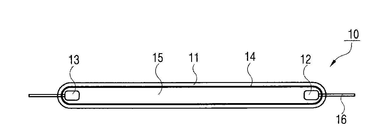
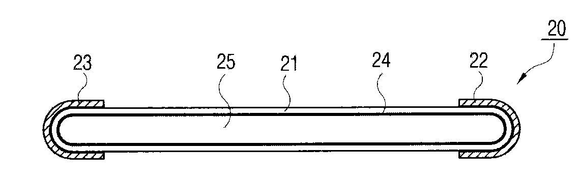
[0019] image 3 A device for baking fluorescent lamps according to an embodiment of the present invention is schematically shown. The fluorescent lamp baking equipment includes: a heater 110, a transfer block 120, and a rotating unit 130'. The heater 110 includes a lower heater 112 and an upper heater 114 . The heater 110 heats the quartz tube (C) from upward and downward directions. Such as Figure 4 As shown, the fluorescent lamp (L) is located inside the quartz tube (C).

[0020] Figure 5 supply image 3 A more detailed diagram along the V-V direction. The rotation unit 130' includes a plurality of rotation rollers 130 placed side by side in a space formed between the lower heater 112 and the upper heater 114. Referring to FIG. A plurality of quartz tubes C each having a fluorescent lamp L therein are placed on the upper portion of the rotating roller 130 . The lower heater 112 and the upper heater 114 heat the quartz tube passing therebetween, thereby baking the f...


PUM


Abstract

This disclosure relates to an apparatus and a method for making or baking a fluorescent lamp. An apparatus for baking a fluorescent lamp includes a heater to heat a plurality of quartz tubes. Each tube has a fluorescent lamp provided therein. A plurality of rollers rotates the quartz tubes placed thereon, and a transfer block has a plurality of auxiliary rollers. The transfer block is configured to move in a first direction to transfer the plurality of quartz tubes from the plurality of rotating rollers to the plurality of auxiliary rollers. A process for heating at least one fluorescent lamp includes a step of providing a plurality of quartz tubes on a plurality of rotating rollers, at least one quartz tube having a fluorescent lamp provided therein, heating the plurality of quartz tubes while being rotated on the plurality of rollers, and transferring the plurality of quartz tube using a transfer block having a plurality of auxiliary rollers.

Description

technical field [0001] The present invention relates to an apparatus and method for manufacturing a fluorescent lamp, and more particularly, to an apparatus and method for baking a fluorescent lamp. Background technique [0002] Thin tube lamps are widely used as backlight sources for LCD panels. The outer diameter of thin tube lamps can be several millimeters. Examples of such narrow tube lamps include cold cathode fluorescent lamps (CCFL) and external electrode fluorescent lamps (EEFL). [0003] The structure of a general cold cathode fluorescent lamp 10 is as follows: figure 1 shown. The cold cathode fluorescent lamp 10 includes a relatively long glass tube 11 , and two electrodes having an anode electrode 12 and a cathode electrode 13 at the ends of the long glass tube 11 . The two electrodes are respectively connected with the lead wires 16 at both ends of the glass tube 11 . In addition, a fluorescent substance 14 is coated on the inner wall of the glass tube 11 ....

Claims


Application Information

Patent Timeline
Patent Type & Authority Applications(China)
IPC IPC(8): H01J9/00H01J9/22B05D3/02
CPCH01J9/46H01J9/39H01J61/52H01J9/22H01J2209/015
Inventor 金玟锡李康钦金泰熙金银石金玟洙
Owner ADVANCED DISPLAY PROCESS ENG
Why Eureka
Try Eureka