Method for laying direct current grounding pole

A DC grounding and grounding electrode technology, applied in the direction of connecting contact materials, etc., can solve the problems of increased project construction costs, increased construction costs, and the reduction of the step voltage of the ground electrode. The size of the ground electrode is not obvious, and achieves Simple and easy to implement, increase the floor area, and increase the effect of construction costs

Inactive Publication Date: 2010-08-25
TSINGHUA UNIV
View PDF0 Cites 0 Cited by
  • Summary
  • Abstract
  • Description
  • Claims
  • Application Information

AI Technical Summary

Problems solved by technology

[0012] 2. Increase the size of the DC grounding electrode
However, increasing the size of the ground electrode means that a larger land area needs to be occupied, more ground electrode materials and more earthwork to be excavated. Not only the construction cost is greatly increased, but in some cases, due to the actual geological conditions Due to the limitation of the available land area, it is impossible to increase the size of the grounding electrode
[0013] 3. Increase the buried depth of the DC grounding electrode
Increasing the buried depth can reduce the maximum step voltage, but it also means that the amount of earthwork that needs to be excavated increases, and the construction cost increases
Moreover, the research and experimental data show that when the burial depth is deeper, the amount of soil that needs to be excavated increases in a series manner, and increasing the burial depth reduces the step voltage of the ground electrode more than increasing the size of the ground electrode, etc. less obvious method

Method used


Image

  • Method for laying direct current grounding pole
  • Method for laying direct current grounding pole
  • Method for laying direct current grounding pole

Examples


Embodiment Construction

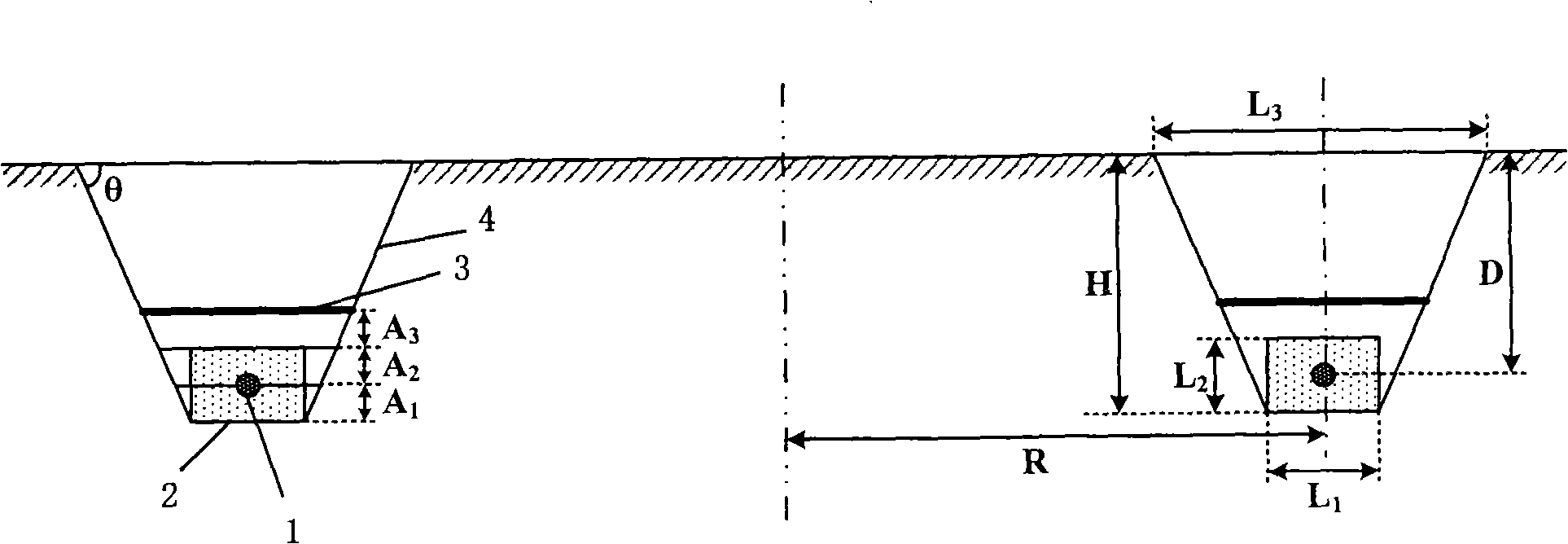
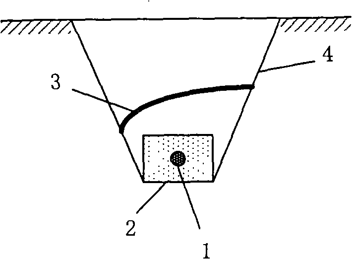
[0029] The embedding method of the DC ground electrode proposed by the present invention, the structure of the embedded circular DC ground electrode is shown in Figure 1, and the embedding process includes the following steps:

[0030] (1) Excavate an annular pit with an isosceles trapezoidal cross section in the soil, the distance between the center line of the trapezoidal section and the center of the circle is equal to the radius R of the circular DC grounding electrode to be buried, and the height H of the trapezoidal section is equal to the The buried depth D of the ground electrode needs to be buried plus the side length L of the rectangular coke section that needs to be wrapped around the ground electrode 2 Half of H=D+1 / 2 L 2 , the length of the bottom side of the trapezoidal section is equal to the length L of the bottom side of the rectangular coke section to be wrapped 1 , the length of the top side of the trapezoidal section is determined by the length of the bott...


PUM


Abstract

The invention relates to a method for laying a direct current grounding pole, which belongs to the grounding technology of electric power system in the field of electrician. The method comprises the following steps of firstly digging a ring-shaped pit with an isosceles trapezoid cross section in soil, paving a coke layer on the bottom of the ring-shaped pit, embedding the direct current groundingpole over the coke layer and laying a coke layer with the same thickness as the below space of the grounding pole over the direct current grounding pole; and then paving an soil layer over the coke layer, paving an insulation layer over the soil layer, and finally back-filling the soil over the insulation layer so as to lead the soil to be flat with the surrounding ground. The method for laying the direct current grounding pole provided by the invention has the advantage that the laying process is simple and easy to be operated, and the step voltage of the direct current grounding pole can bereduced by only adding a layer of insulation layer in the process of paving the direct current grounding pole. The laying method does not enlarge the occupied area of the direct current grounding pole, does not increase the size of the grounding pole, nor increases the construction cost, thereby needing less investment in economy compared with the existing laying method.

Description

technical field [0001] The invention relates to a method for embedding a DC grounding electrode, which belongs to the grounding technology of electric power systems in the field of electric engineering. Background technique [0002] The DC grounding electrode is an important part of the DC transmission system, and its performance is directly related to the safety of the DC transmission system. The parameters of the DC grounding electrode include grounding resistance, maximum ground potential rise, maximum step voltage, maximum transfer potential, current density and design life, etc. The parameters of the DC grounding electrode need to meet the requirements of the system and personal safety. [0003] When the current of the DC transmission system flows into the ground through the DC grounding electrode, a certain potential distribution will be generated on the surrounding ground surface. According to my country's electric power industry standard DL / T 5224-2005 "Technical Re...

Claims


Application Information

Patent Timeline
Patent Type & Authority Patents(China)
IPC IPC(8): H01R4/66
Inventor 何金良陈凡高理迎卢理成曾嵘刘泽洪张波
Owner TSINGHUA UNIV
Why Eureka
Try Eureka