Connector

A connector and electrical connection technology, which is applied in the direction of connection, parts of connection devices, high-frequency structural connection, etc., can solve problems such as poor contact, increased production cost and time, and deformation of signal pins

Inactive Publication Date: 2009-10-07
DELTA ELECTRONICS INC
View PDF0 Cites 2 Cited by
  • Summary
  • Abstract
  • Description
  • Claims
  • Application Information

AI Technical Summary

Problems solved by technology

However, no matter which method is used above, additional components and manufacturing processes are required to electrically connect the steel shell and the circuit board, so the production cost and time are greatly increased.
In addition, there is still a technology of welding the clip feet on the inside of the steel shell. However, because this technology uses the clip feet to elastically clip the circuit board, it is very prone to the problem of poor contact.
If you want to weld the aforementioned clips on the circuit board after the clips are connected to the circuit board, there will be difficulties in the manufacturing process because the solder joints will be blocked by the steel shell or the circuit board.
[0004] In addition, when the signal pins are inserted into the plastic seat of RJ-45, cracks often occur on the plastic seat, causing the signal pins to be unable to be firmly fixed on the plastic seat, and even causing the signal pins to deform or break

Method used


Image

  • Connector
  • Connector
  • Connector

Examples


Embodiment Construction

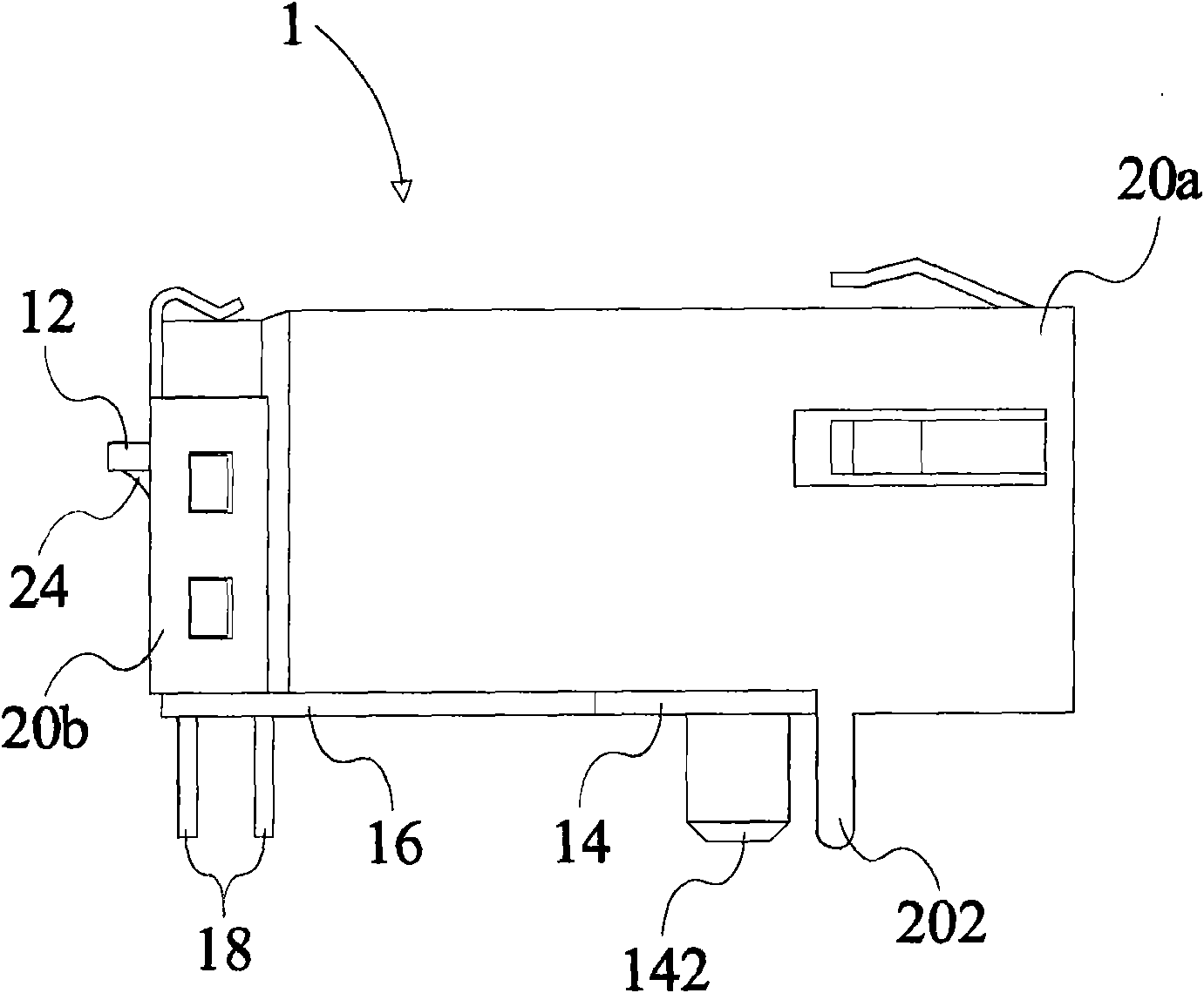
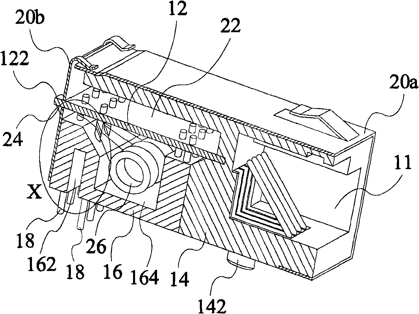
[0030] A preferred embodiment of a connector 1 of the present invention is figure 1 and figure 2 shown. figure 2 It is a three-dimensional cross-sectional view of the connector 1 of the present invention. The connector 1 includes a body and a circuit board 12 . The body includes a shell and a base. The casing can be composed of a main cover 18a and a back cover 18b, and the casing can be a metal shell. The shell covers the base. The base can be divided into a first base 14 and a second base 16, the first base 14 has a receiving space S2 used as a connection port and the first base 14, the second base 16 and The housing surrounds an accommodating space S1. The connector 1 can be an RJ-45 connector, an RJ-11 connector or a USB connector.

[0031] In addition, the back cover 18b can be connected to the main cover 18a by hooking at the rear end of the main cover 18a. The connector 1 of the present invention further includes a connecting terminal 20, which is arranged in ...


PUM


Abstract

The invention discloses a connector which comprises a main body and a circuit board. The main body comprises an accommodation space and a casing. The circuit board is arranged in the accommodation space, and one part of the circuit board is provided with a grounding circuit region, one part of the circuit board protrudes out of the casing, and the casing is electrically connected with the grounding circuit region.

Description

technical field [0001] The present invention relates to a connector, and more particularly to a connector having a second base that effectively and stably holds pins. Background technique [0002] The traditional grounding methods of RJ-45 connectors integrating network applications are mostly the following two: one is to connect the high-voltage capacitor to the signal pin of the physical layer, and achieve the purpose of grounding through the signal pin; the other is to connect the high-voltage capacitor to the steel shell, and then The purpose of grounding is achieved through the grounding pin of the steel shell itself. [0003] Among them, the connection method between the high-voltage capacitor and the steel shell is that the circuit board completely covered in the RJ-45 connector is welded to the steel shell through the capacitor wire, the capacitor pin, the pull wire or the pin welded to the steel shell. grounding effect. However, no matter which method is used abov...

Claims


Application Information

Patent Timeline
Patent Type & Authority Applications(China)
IPC IPC(8): H01R13/66H01R13/719H01R13/40H01R13/506
Inventor 张中明戴毓元
Owner DELTA ELECTRONICS INC
Why Eureka
Try Eureka