Bridgeless power factor circuit correcting circuit system used for critical conduction mode and control method thereof

A technology for power factor correction and power correction, which is applied in output power conversion devices, electrical components, sustainable manufacturing/processing, etc., and can solve problems such as large losses

Active Publication Date: 2009-10-07
DELTA ELECTRONICS INC +1
View PDF0 Cites 44 Cited by
  • Summary
  • Abstract
  • Description
  • Claims
  • Application Information

AI Technical Summary

Problems solved by technology

[0008] Figure 7 Yes Figure 5 The shown circuit is under the condition of high input voltage and full load (264Vin, 310W load) and the waveform of the detection failure of the inductor current to zero. It shows that the current has not reached zero, and the switch is turned on, resulting in a large loss related to it.

Method used


Image

  • Bridgeless power factor circuit correcting circuit system used for critical conduction mode and control method thereof
  • Bridgeless power factor circuit correcting circuit system used for critical conduction mode and control method thereof
  • Bridgeless power factor circuit correcting circuit system used for critical conduction mode and control method thereof

Examples


Embodiment Construction

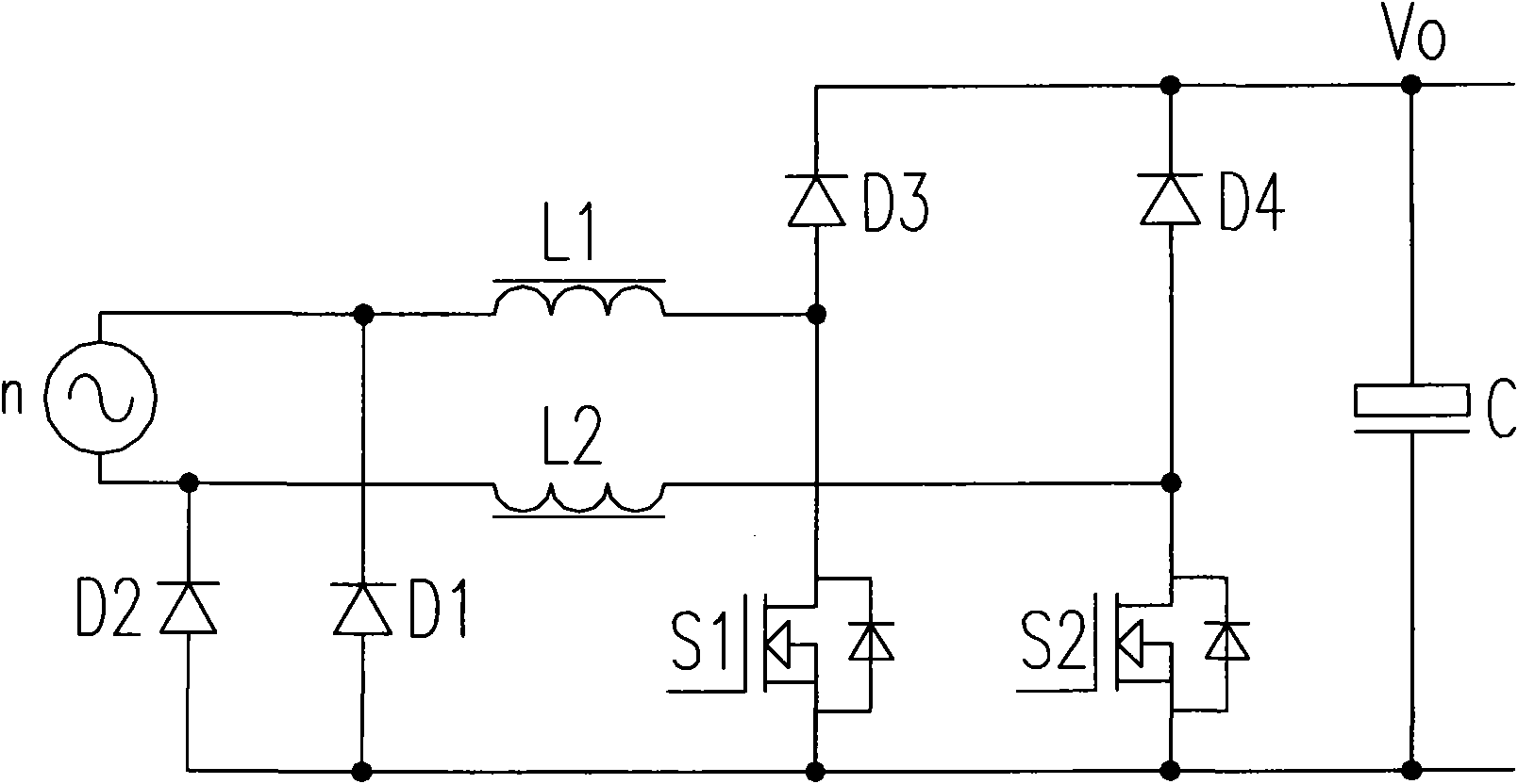
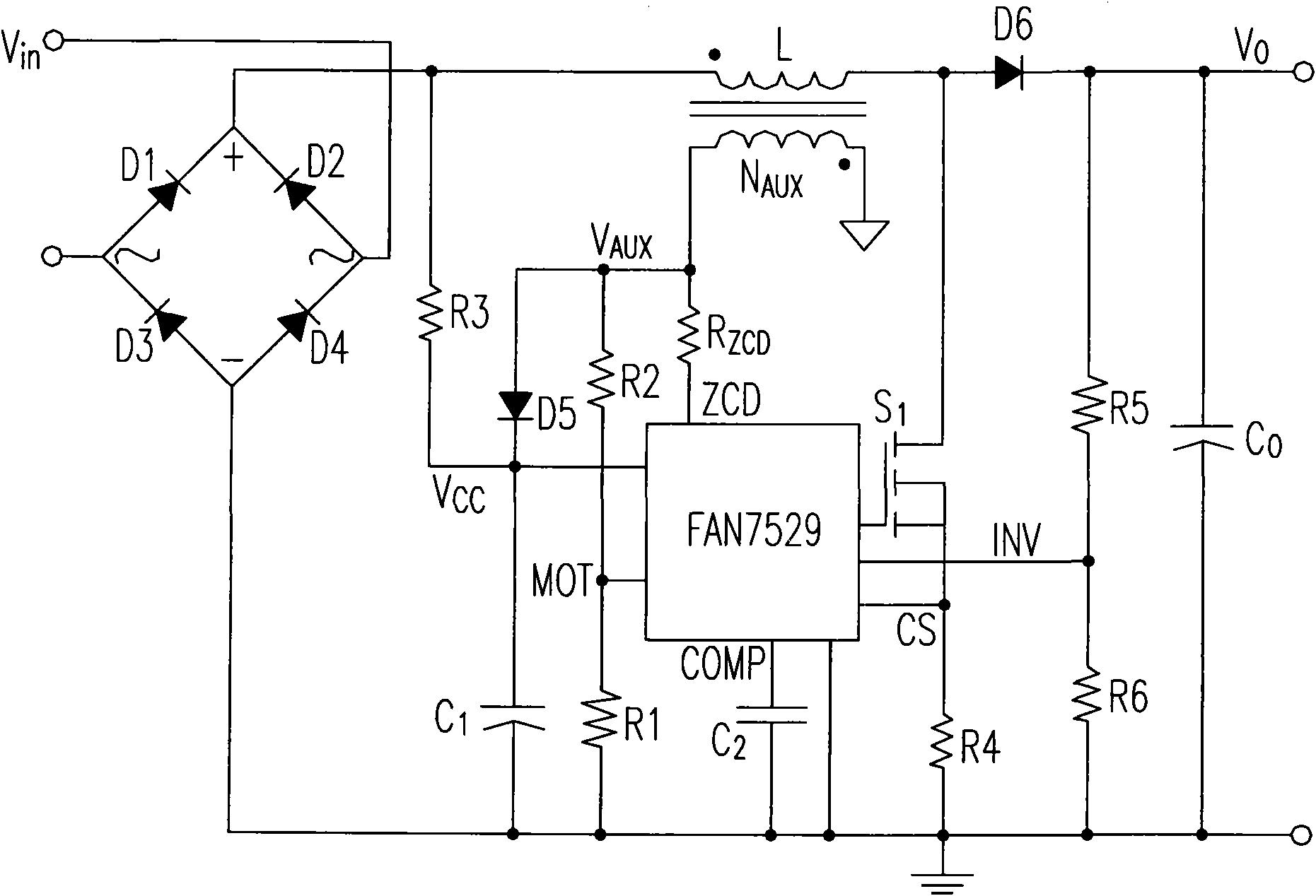
[0039] In the Dual Boost PFC circuit shown in Figure 4(a)-(b), although current flows through both inductors at the same time at each moment, when any inductor works as a boost inductor, the voltage of the other inductor Clamp the conduction voltage drop of diode D1 or D2 in the circuit. Because the conduction voltage drop is very small, the amplitude is close to zero after being converted to the auxiliary winding of the inductor after the conversion ratio, and the other auxiliary winding of the inductor works in a boost mode. According to this feature, it is possible to use image 3 The method of detecting the auxiliary winding voltage of the boost inductor to realize the critical conduction mode control is to superpose the voltages induced by the two auxiliary windings of the inductor through two resistors R1 and R2 with the same resistance value respectively.

[0040] Figure 8 Shown is a schematic circuit diagram of a Dual Boost PFC utilizing two inductive auxiliary wind...


PUM


Abstract

The invention discloses a bridgeless power factor circuit correcting circuit system used for critical conduction mode and a control method thereof. The bridgeless power factor circuit correcting circuit system comprises a bridgeless power factor correcting circuit, a first auxiliary winding and a second auxiliary winding, wherein the bridgeless power factor correcting circuit comprises a first switch, a first inductance and a second inductance; the first auxiliary winding is coupled to the first inductance and produces a first sensing signal; the second auxiliary winding is coupled to the second inductance and produces a second sensing signal, the first sensing signal and the second sensing signal are used for producing an inductance current detection signal; meanwhile, when the value of the inductance current detection signal is zero, the first switch is connected.

Description

technical field [0001] The invention discloses a bridgeless power factor correction circuit (Bridgeless PFC) for a critical conduction mode (Critical Conduction Mode) and a control method thereof, which can be used to solve the control problem of the critical conduction mode of the bridgeless PFC. Background technique [0002] The loss of the rectifier bridge in the traditional boost power factor correction circuit (Boost PFC) circuit becomes one of the main losses of the whole switching power supply. As the requirements for conversion efficiency increase, the bridgeless Boost topology derived from the traditional Boost PFC topology has gradually become the focus of research. It omits the rectifier bridge at the front end of the Boost PFC, reduces the on-state loss of a diode, and improves efficiency. The dual boost power factor correction circuit (Dual Boost PFC, DBPFC) is a bridgeless PFC topology suitable for medium and high power (see figure 1 ). exist figure 1 Among...

Claims


Application Information

Patent Timeline
Patent Type & Authority Applications(China)
IPC IPC(8): H02M1/42
CPCY02B70/126Y02B70/10Y02P80/10
Inventor 隋鲁波金红元甘鸿坚
Owner DELTA ELECTRONICS INC
Why Eureka
Try Eureka