High efficiency power drive device enabling serial connection of light emitting diode lamps thereto

a technology of power drive and led lamps, which is applied in the direction of lighting apparatus, electroluminescent light sources, light sources, etc., can solve the problems of unsatisfactory unusable switching power supplies used by computers not only using a great many components, and affecting the service life of led lamps. , to achieve the effect of prolonging the service li

Inactive Publication Date: 2011-11-17
MAIW FU HWA
View PDF0 Cites 42 Cited by
  • Summary
  • Abstract
  • Description
  • Claims
  • Application Information

AI Technical Summary

Benefits of technology

[0015]In addition, the present invention utilizes the PFC circuit using the ST L6561 chip to achieve the so-called Transition Mode Technique to obtain the voltage required by the LED lamps when serially connected, and uses current control to achieve enabling the input current to have a sinusoidal wave form, as well as achieving the objective of phase equality between the current and voltage. Moreover, a current control IC with serial number 9910 of the LED constant current drive circuit is used to eliminate the need to adopt an

Problems solved by technology

For example, operating current of the LED lamps gradually rises as the number of hours of use increases, finally resulting in a flicker phenomenon appearing in the LED lamps because of an inadequate output current from the switching power supply, and such phenomenon is often seen in traffic signs using LED lamps at road intersections.
Furthermore, because sets of LED lamps in the current market are limited to using power supply devices that provide low voltage high current output, thus, the majority of arrangements of the LED lamps adopts a parallel connection method, and the passing current produced by the parallel connection is inconsistent and often causes nonuniform brightness to occur in the LED lamps, which at the same time results in an unequal serviceabl

Method used


Image

  • High efficiency power drive device enabling serial connection of light emitting diode lamps thereto
  • High efficiency power drive device enabling serial connection of light emitting diode lamps thereto
  • High efficiency power drive device enabling serial connection of light emitting diode lamps thereto

Examples


Embodiment Construction

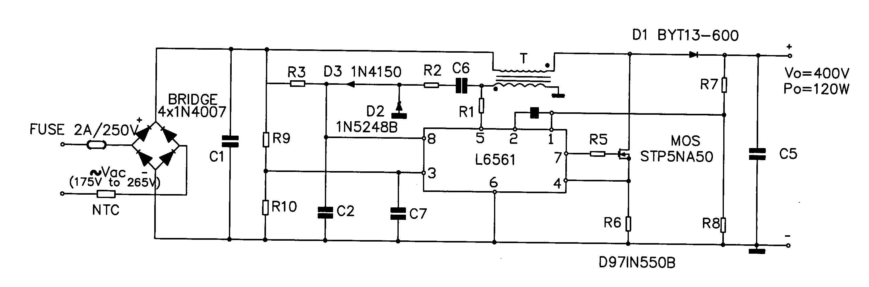
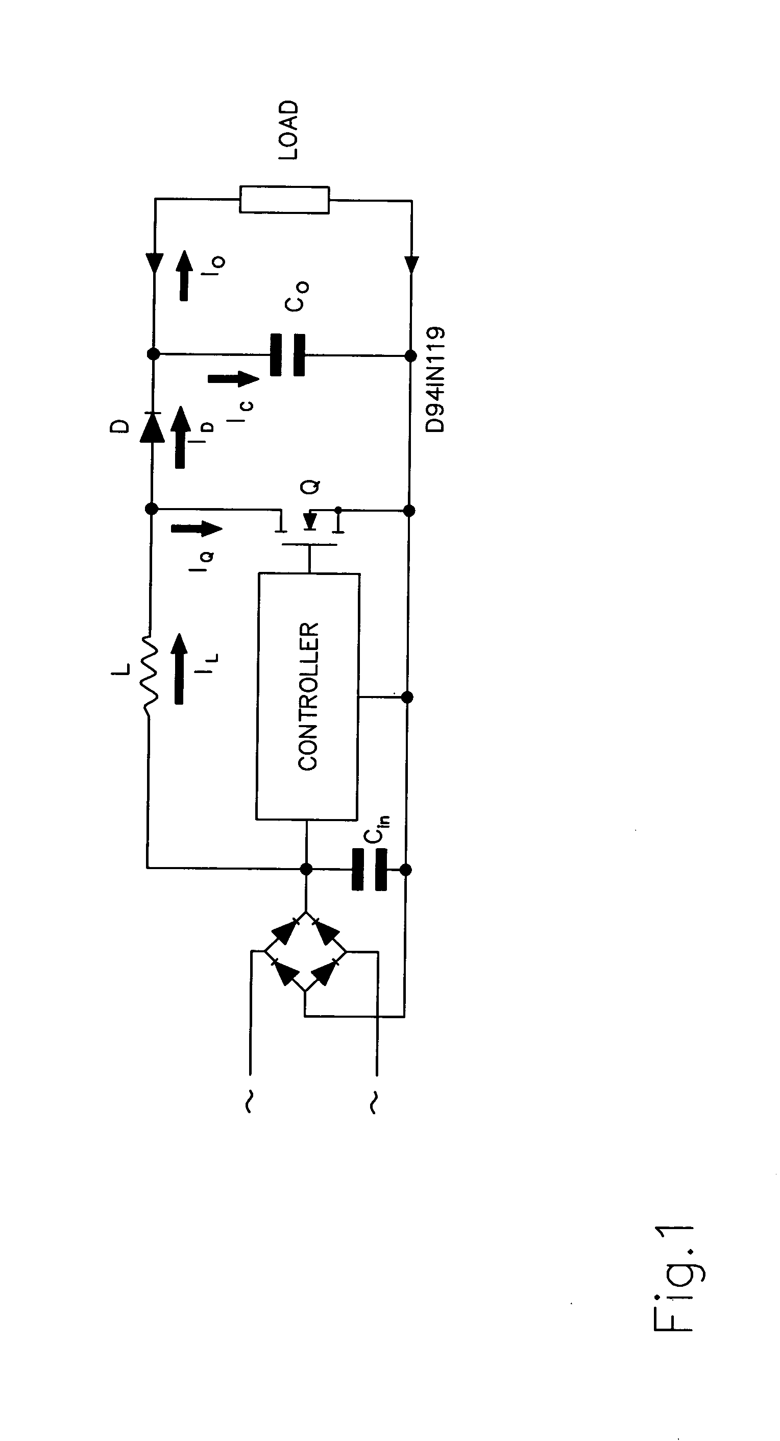
[0023]Referring to FIG. 1, FIG. 3 and FIG. 4, FIG. 5 and FIG. 6, which show a high efficiency power drive device enabling serial connection of LED lamps thereto of the present invention, wherein a power drive circuit comprises:

[0024]A power source filter circuit EMI / EMC, which primarily intercepts noise signals produced by electric current provided by an alternating current J1 through a common mode and a passive low-pass network to a nodal point where they cancel out and an earth reference potential. Because the power source filter circuit EMI / EMC uses a voltage range compatible with power systems worldwide as the basis for its voltage range, thus, the power source filter circuit EMI / EMC is applicable for use in the power supply system of all countries. Accordingly, no modifications whatsoever are required regardless of the location in the world.

[0025]An AC to DC rectifier, which converts alternating current provided by the alternating current J1 into direct current for use thereof ...


PUM


Abstract

A high efficiency power drive device enabling serial connection of LED lamps thereto, which includes a power source filter circuit, an AC to DC rectifier, a power factor correction circuit and an LED constant current drive circuit. The power factor correction circuit is utilized using the so-called transition mode technique to obtain voltage required by the LED lamps when serially connected, and current control is used to achieve a state whereby the current and voltage are in the same phase. A current control IC and an externally set resistor are further used to eliminate the need to adopt any CPU (central processing unit) while accurately directly controlling the output pulse width of PWM (Pulse Width Modulation).

Description

BACKGROUND OF THE INVENTION[0001](a) Field of the Invention[0002]The present invention relates to a high efficiency power drive device enabling serial connection of LED (Light Emitting Diode) lamps thereto, and more particularly to a power drive device which has low cost, is high energy saving, has a long serviceable life and extensive and exhaustive application, and which is applicable for use in connection with a set of LED lamps installed in a lamp when illuminating. The power drive device uses a power source filter circuit to intercept noise signals of the system, when operating, through a common mode and a passive low-pass network to a nodal point where they cancel out and an earth reference potential. An AC (Alternating Current) to DC (Direct Current) rectifier included in the present invention primarily functions to convert alternating current into direct current, and then a power factor correction circuit is utilized using an L6561 chip to achieve a design using the so-calle...

Claims


Application Information

Patent Timeline
IPC IPC(8): H05B37/02
CPCH05B33/0809H05B45/38Y02B20/30
Inventor MAIW, FU-HWA
Owner MAIW FU HWA
Why Eureka
Try Eureka