Single-phase and three-phase dual buck-boost/buck power factor correction circuits and controlling method thereof

a power factor correction and circuit technology, applied in power conversion systems, climate sustainability, energy industry, etc., can solve problems such as polluting the grid, public nuisance, and inability to adapt single-stage boost circuits, and achieve the effects of improving the efficiency of the same, and improving the thd of the three-phase dual buck-boost/buck circui

Active Publication Date: 2010-10-07
DELTA ELECTRONICS INC
View PDF8 Cites 41 Cited by
  • Summary
  • Abstract
  • Description
  • Claims
  • Application Information

AI Technical Summary

Benefits of technology

[0012]It is therefore an object of the present invention to provide single-phase/three-phase dual buck-boost/buck circuits and a controlling method thereof, which can be employed to solve the problem that the boost diode of the conventional single-phase dual buck-boost/buck circuit has a relatively higher conduction loss while operating under a buck mode. The three-phase dual buck-boost/buck circuit comprises three independent single-phase dual buck-boost/buck circuits, and the three single-phase dual buck-boost/buck

Problems solved by technology

Due to the rectifier, lots of current harmonics and reactive power are generated in the grid, which pollute the grid and become a public nuisance.
For those application occasions

Method used


Image

  • Single-phase and three-phase dual buck-boost/buck power factor correction circuits and controlling method thereof
  • Single-phase and three-phase dual buck-boost/buck power factor correction circuits and controlling method thereof
  • Single-phase and three-phase dual buck-boost/buck power factor correction circuits and controlling method thereof

Examples


Embodiment Construction

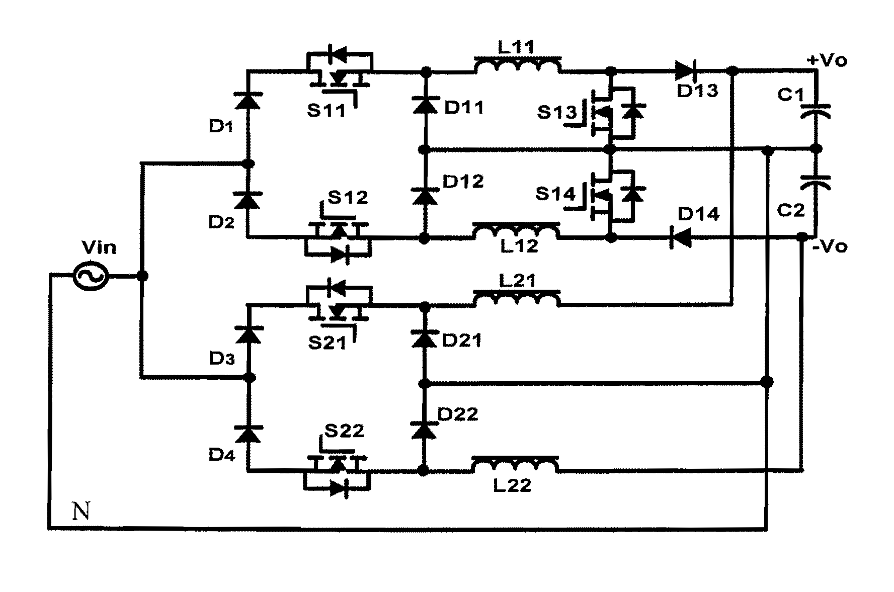
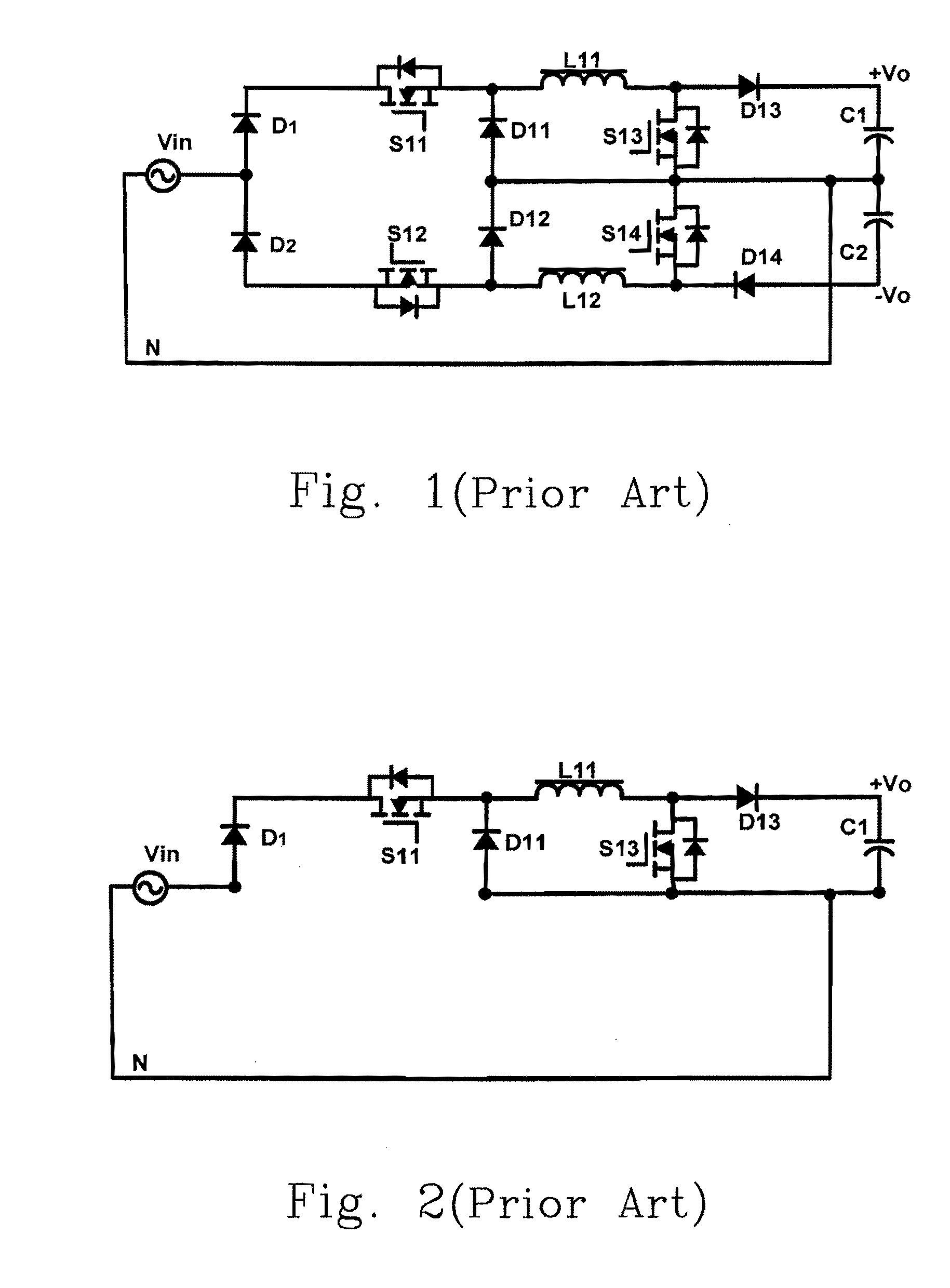
[0042]To overcome the drawbacks of the conventional buck-boost PFC circuits as aforementioned, an improved topology of the dual buck-boost / buck circuit as shown in FIG. 4 of the present invention is provided. In FIG. 4, the circuit could be viewed as having two portions. The upper half portion is a buck-boost circuit, and the lower half portion is a buck circuit. FIG. 4 has the diodes Di, Dj1-Dj2, D13-D14, the switches Sj1-Sj2, S13-S14, the inductors Lj1-Lj2 (in which, i=1˜4, j=1˜2), a first output capacitor C1, a second output capacitor C2 and a neutral line N. The converter in FIG. 4 can be used as a PFC converter.

[0043]The first output capacitor C1 connects to a first output terminal and a neutral-point; the second output capacitor C2 connects to the neutral-point and a second output terminal; and the neutral line N connects the neutral point of the input power source Vin (e.g. an AC voltage) and the neutral-point. The dual buck-boost / buck circuit generates its first and second o...


PUM


Abstract

The configurations of a single-phase dual buck-boost/buck power factor correction (PFC) circuit and a controlling method thereof are provided in the present invention. The proposed circuit includes a single-phase three-level buck-boost PFC circuit receiving an input voltage and having a first output terminal, a neutral-point and a second output terminal for outputting a first and a second output voltages, a single-phase three-level buck PFC circuit receiving the input voltage and coupled to the first output terminal, the neutral-point and the second output terminal, a first output capacitor coupled to the first output terminal and the neutral-point, a second output capacitor coupled to the neutral-point and the second output terminal, and a neutral line coupled to the neutral-point.

Description

FIELD OF THE INVENTION[0001]The present invention relates to single-phase / three-phase dual buck-boost / buck power factor correction (PFC) circuits and a controlling method thereof. More particularly, it relates to a single-phase dual buck-boost / buck PFC circuit having a single-phase three-level buck-boost PFC circuit and a single-phase three-level buck PFC circuit, which can be employed to solve the problem that the boost diode of the conventional single-phase dual buck-boost / buck PFC circuit has a relatively higher conduction loss when it is operates under a buck mode, to improve the total harmonic distortion (THD) of a three-phase three-level buck-boost PFC circuit, and to increase an efficiency of the same.BACKGROUND OF THE INVENTION[0002]In the recent twenty years or so, the power electronic technology has obtained a rapid development, and has been widely applied to the fields of electrical power, chemical engineering and communications. The electrical power apparatus generally r...

Claims


Application Information

Patent Timeline
IPC IPC(8): G05F1/70
CPCH02M1/42Y02B70/126Y02B70/12H02M1/4216Y02B70/10Y02P80/10
Inventor TAN, JINGTAOZHOU, ZHIJIANYANG, JIANPINGGOU, WENHUIYING, JIANPING
Owner DELTA ELECTRONICS INC
Why Eureka
Try Eureka