Power factor correction circuit

a technology of power factor and circuit, applied in the direction of electric variable regulation, process and machine control, instruments, etc., can solve the problems of abnormal state, increase the cost of the circuit, increase the size of the circuit, etc., to increase the circuit cost, reduce the risk, and increase the circuit size

Active Publication Date: 2009-11-26
SANKEN ELECTRIC CO LTD
View PDF7 Cites 45 Cited by
  • Summary
  • Abstract
  • Description
  • Claims
  • Application Information

AI Technical Summary

Benefits of technology

[0014]The power factor correction circuit of the first related art illustrated in FIG. 1 should employ the second winding N2 that is an auxiliary winding of the transformer T1. The auxiliary winding in...

Problems solved by technology

The auxiliary winding increases the size of the circuit and has a risk of causing an abnormal state such as short-circuited.
To reduce the risk, the first related art must take some measure that may increase the cost of the circuit.
If the input voltage su...

Method used


Image

  • Power factor correction circuit
  • Power factor correction circuit
  • Power factor correction circuit

Examples


embodiment 1

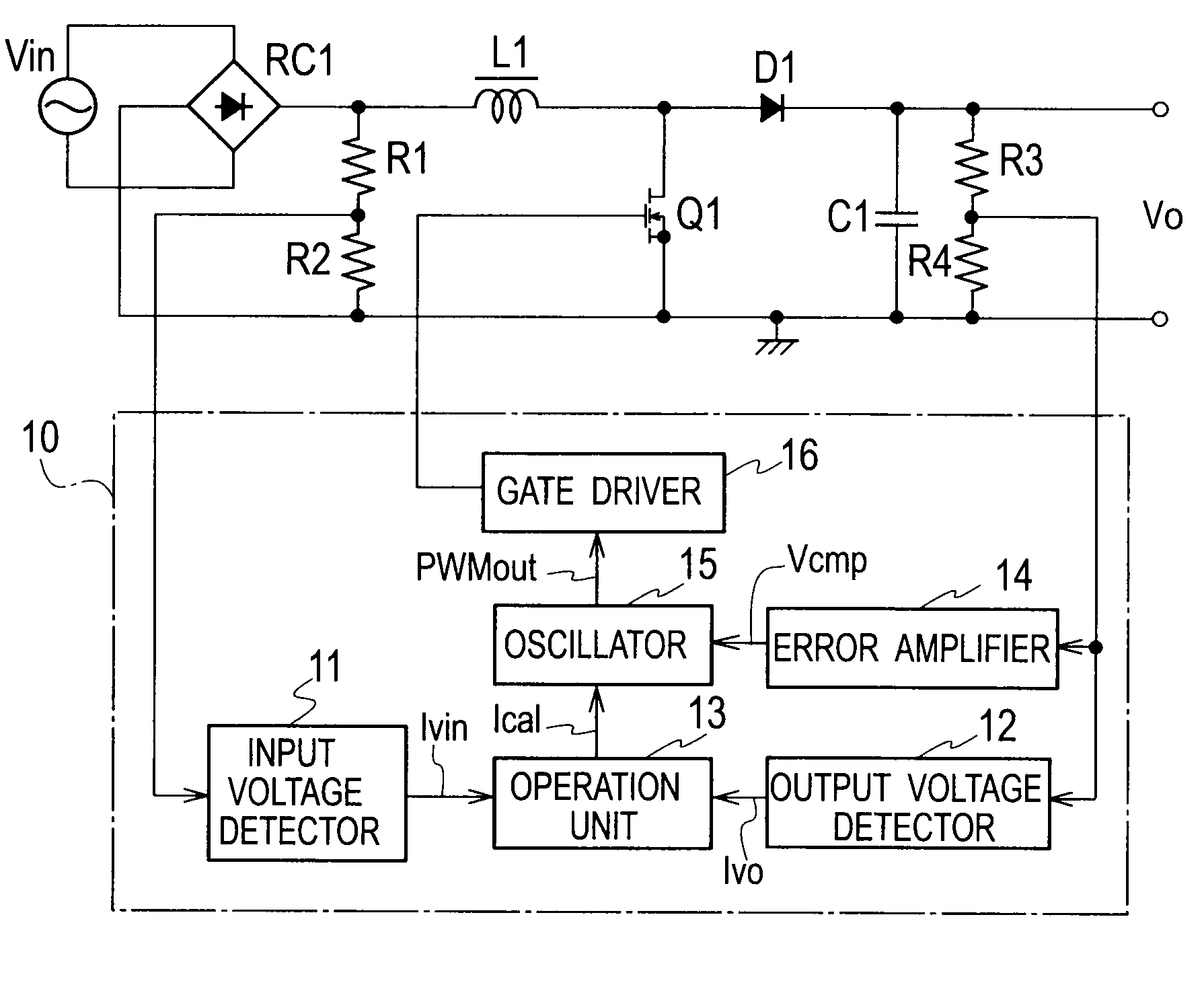
[0036]FIG. 4 is a circuit diagram illustrating a power factor correction circuit according to Embodiment 1 of the present invention. The circuit includes a first rectifier RC1 to rectify and convert an AC voltage of an AC power source Vin into a DC voltage. An output of the first rectifier RC1 is connected to a series circuit including a step-up reactor L1 and a switching element Q1 made of an n-type MOSFET. Both ends of the switching element Q1 are connected in parallel with a rectifying-smoothing circuit including a second rectifier D1 and a smoothing capacitor C1. A voltage across the first rectifier RC1 is connected to a series circuit including resistors R1 and R2. Both ends of the smoothing capacitor C1 are connected to a series circuit including resistors R3 and R4.

[0037]A controller 10 controls an ON / OFF operation of the switching element Q1 and includes an input voltage detector 11, an output voltage detector 12, an operation unit 13, an error amplifier 14, an oscillator 15...

embodiment 2

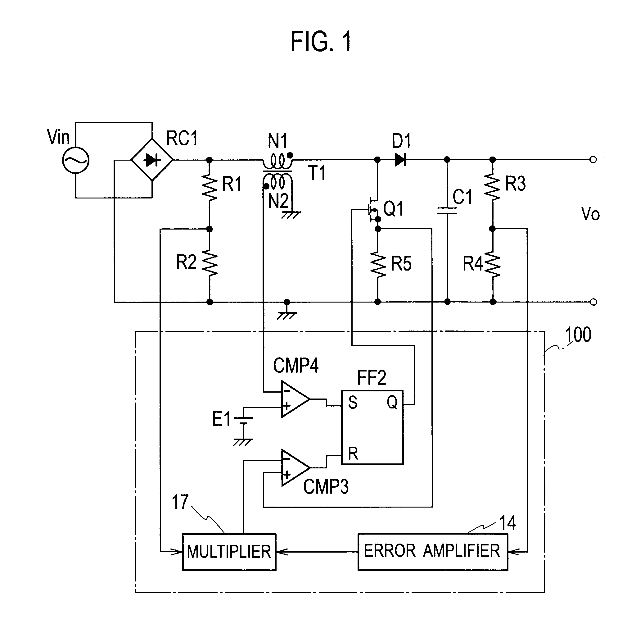
[0079]FIG. 11 is a circuit diagram illustrating a power factor correction circuit according to Embodiment 2 of the present invention. Embodiment 2 differs from Embodiment 1 in that it employs a control circuit 10a of different configuration. Accordingly, only the control circuit 10a will be explained.

[0080]In FIG. 11, the control circuit 10a includes an input voltage detector 11, an output voltage detector 12, an error amplifier 14, an oscillator 15a, a gate driver 16, and a multiplier 17.

[0081]The input voltage detector 11 converts a divided input voltage signal Vvin into an input voltage signal Ivin and provides the oscillator 15a with the input voltage signal Ivin. Here, the divided input voltage signal Vvin is obtained by dividing an output voltage of a first rectifier RC1 by resistors R1 and R2. The input voltage signal Ivin is a current signal proportional to the output voltage of the first rectifier RC1. The divided input voltage signal Vvin is also supplied to the multiplier...


PUM


Abstract

A power factor correction circuit includes a first rectifier to rectify an AC voltage, a series circuit connected to an output of the first rectifier and including a step-up reactor and a switching element, a rectifying-smoothing circuit connected to both ends of the switching element and including a second rectifier and a smoothing capacitor, an input voltage detector to detect an output voltage of the first rectifier, an output voltage detector to detect a voltage across the smoothing capacitor, an error amplifier to amplify an error between the output voltage signal and a reference voltage, and a controller to determine an ON/OFF duty ratio of the switching element according to the amplified error signal and a result of a calculation carried out on the input voltage signal and output voltage signal.

Description

BACKGROUND OF THE INVENTION[0001]1. Field of the Invention[0002]The present invention relates to a technique of controlling a power factor correction circuit.[0003]2. Description of the Related Art[0004]FIG. 1 is a circuit diagram illustrating a power factor correction circuit according to a first related art. This power factor correction circuit is with a current-critical, step-up DC / DC converter.[0005]In FIG. 1, a first rectifier RC1 rectifies and converts an AC voltage of an AC power source Vin into a DC voltage. An output of the first rectifier RC1 is connected to a series circuit including a first winding N1 of a step-up transformer T1, a switching element Q1 made of an n-type MOSFET, and a resistor R5. A series circuit of the switching element Q1 and resistor R5 is connected in parallel with a rectifying-smoothing circuit including a second rectifier D1 and a smoothing capacitor C1. Both ends of the first rectifier RC1 are connected to a series circuit of resistors R1 and R2. ...

Claims


Application Information

Patent Timeline
IPC IPC(8): H02M7/06
CPCY02B70/126H02M1/4225Y02B70/10Y02P80/10
Inventor OSAKA, SHOHEI
Owner SANKEN ELECTRIC CO LTD
Why Eureka
Try Eureka