
Power factor correction circuit

a technology of power factor and correction circuit, applied in the direction of electric variable regulation, process and machine control, instruments, etc., can solve the problems of high cost and high power consumption, and achieve the effect of reducing the distortion of input curren

Active Publication Date: 2009-05-26
SEMICON COMPONENTS IND LLC
View PDF32 Cites 41 Cited by
  • Summary
  • Abstract
  • Description
  • Claims
  • Application Information

AI Technical Summary

Benefits of technology

The present invention provides a power factor correction circuit that reduces distortion of an input current without adding circuit elements such as resistors. The circuit includes a first inductor and a switch that is turned on when a current flowing to the first inductor reaches zero from a positive value. The circuit also includes a secondary winding wire and a switching controller that controls the duration of a turn-on interval of the switch based on a second voltage induced in the secondary winding wire. The turn-on interval is set to be longer if the second voltage is a smaller negative value. This circuit design helps to improve the power factor of the input current and reduce distortion.

Problems solved by technology

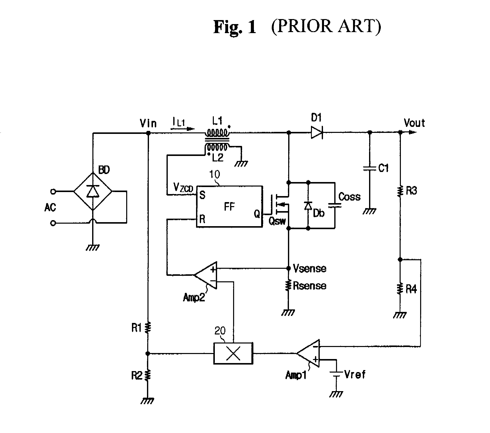
However, in this method, an additional circuit is required, including a plurality of resistors to modify the rectified input voltage, which results in both high cost and high power consumption.

Method used


Image

  • Power factor correction circuit
  • Power factor correction circuit
  • Power factor correction circuit

Examples


Embodiment Construction

[0035]The embodiments of the present invention and their advantages are best understood by referring to FIGS. 4 through 10 of the drawings. Like numerals are used for like and corresponding parts of the various drawings.

[0036]FIG. 4 is a schematic diagram of an exemplary implementation of power factor correction circuit 10, according to an embodiment of the present invention.

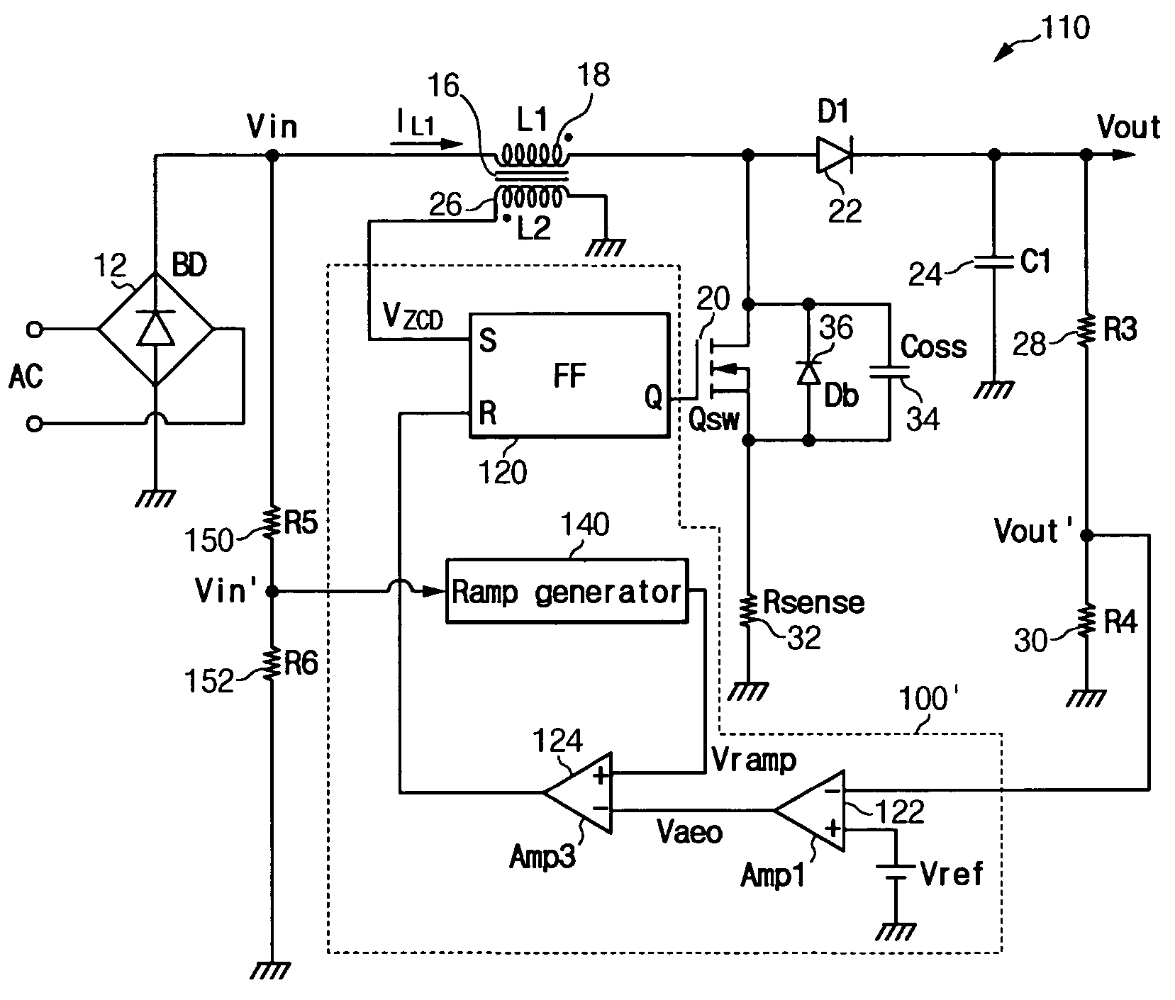
[0037]As depicted, the power factor correction circuit 10 may include a bridge diode BD 12, a boost circuit 14 including a transformer 16 having a primary winding L118, a switch Qsw 20, a diode D122, a capacitor C124, and a switching controller 100. Hereinafter, the inductor 16, a switch Qsw 20, the diode D122, and the capacitor C124 will be referred to as “the boost circuit” for convenience of description.

[0038]The bridge diode BD 12 rectifies an externally input AC voltage and outputs a full-wave rectification voltage Vin. The switching controller 100 receives a sensed output voltage Vout′ and a voltage VZCD i...


PUM


Abstract

The present invention relates to a power factor correction circuit for compensating distortion of an input current. According to the exemplary embodiment of the present invention, a turn-on interval length of a switch is controlled according to a voltage induced in a secondary winding wire of an inductor since the voltage induced in the secondary winding wire has information on an input voltage when the switch is turned on. The turn-on interval length of the switch is reduced when the input voltage is great and is increased when the input voltage is low. Therefore, distortion of the input current may be compensated by controlling the turn-on interval of the switch according to the voltage induced in the secondary winding wire without using an additional circuit for sensing the input voltage.

Description

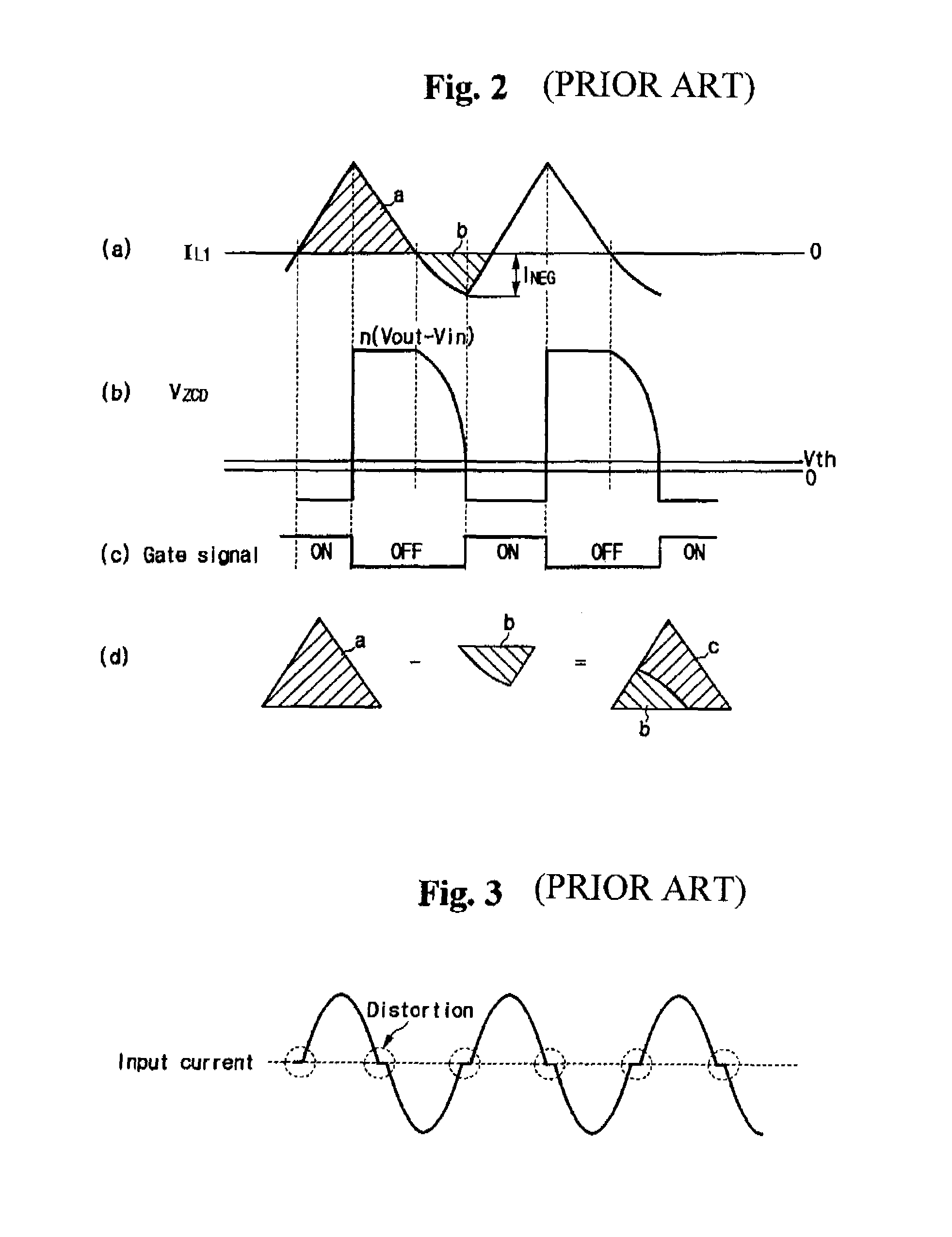
CROSS-REFERENCE TO RELATED APPLICATION[0001]This application claims priority to and the benefit of Korean Patent Application 10-2004-0075538 filed in the Korean Intellectual Property Office on Sep. 21, 2004, the entire content of which is incorporated herein by reference.BACKGROUND OF THE INVENTION[0002](a) Field of the Invention[0003]The present invention relates to a power factor correction circuit, and more particularly, a power factor correction circuit for compensating distortion of an input current.[0004](b) Description of the Related Art[0005]Due to current harmonic limitation standards, such as the EN61000-3-2 standard, power factor correction circuits are used in switching mode power supply (SMPS) devices. The SMPS device is used to convert an input supply voltage into direct output voltages for power supply devices typically found in, for example, mobile telephones and laptop computers. In the SMPS device, a power factor correction circuit is used for compensating power fa...

Claims


Application Information

Patent Timeline
Patent Type & Authority Patents(United States)
IPC IPC(8): G05F1/70G05F1/00H02M3/155H02M7/06
CPCG05F1/70H02M1/4225H02M2001/0022H02M2001/0025Y02B70/126Y02B70/10H02M1/0022H02M1/0025H02M3/28H02M3/155
Inventor KIM, JUNG-WONKIM, DONG-HEE
Owner SEMICON COMPONENTS IND LLC
Learn More