Layered electrically conductive structure and potentiometer comprising such a structure

一种导电材料、薄层的技术,应用在包括多个电阻元件的电阻元件、滑动接触电阻器、抽头的固定电阻器装置等方向,能够解决石墨过热、材料恶化、破裂等问题

Inactive Publication Date: 2009-10-07
ABB RES LTD
View PDF0 Cites 4 Cited by
  • Summary
  • Abstract
  • Description
  • Claims
  • Application Information

AI Technical Summary

Problems solved by technology

However, graphite can locally overheat when an uneven current is applied due to its poor ability to distribute current evenly
As a result, hot spots develop and the material deteriorates or possibly even cracks

Method used


Image

  • Layered electrically conductive structure and potentiometer comprising such a structure
  • Layered electrically conductive structure and potentiometer comprising such a structure

Examples


Embodiment Construction

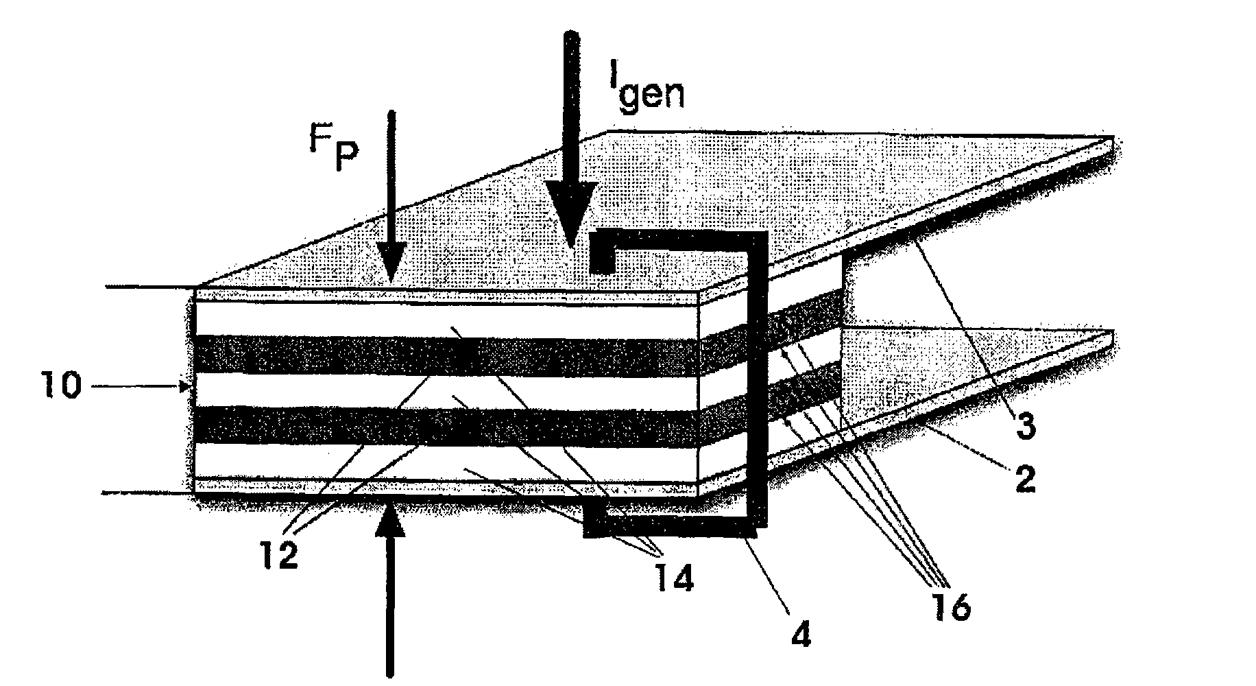
[0012] figure 1 is a perspective view of a conductive resistor 1 according to the invention. The resistor 1 has a bottom plate 2 and a top plate 3 . This resistor 1 further has a conductive laminated body 10 . The conductive stack 10 includes a plurality of conductive metal layers 12 , and a plurality of further conductive layers 14 . exist figure 1 , the layers 12, 14 are arranged on a horizontal plane. This laminate 10 makes it possible to produce highly anisotropic resistors in which the resistance along a direction perpendicular to the layers 12 , 14 is much higher than in the plane of the layers 12 , 14 .

[0013] In the exemplary configuration, the high resistance in the direction perpendicular to the layers 12, 14 may be due to high contact resistance between adjacent layers. A high contact resistance can be caused by a high lumped resistance if the effective contact surface across which the current flows from one layer to another is small; by surface contamination...


PUM


Abstract

The invention relates to an electrical resistor (1) comprising an electrically conductive stack (10), which comprises a plurality of metal first layers (12) and second layers (14). The stack 10 allows to produce a highly anisotropic resistor (1), in which the resistance in the direction perpendicular to the layers (12, 14) is much higher than in the plane of the layers (12, 14). The anisotropy allows the current flowing through the stack (10) to be made homogenous, i.e. to be distributed over the entire stack surface, even if the current is input into the stack (10) in an inhomogenous manner.

Description

technical field [0001] This invention is in the field of conductive materials and generally relates to resistors. More particularly, it relates to resistors having a conductive stack comprising, inter alia, a plurality of metal layers. Background technique [0002] Many applications in power and automation technology require resistive materials whose resistance value or resistivity can be adjusted. Depending on the application, the resistive material should carry rated and fault currents, eg, up to at least tens of kA or more, and support voltages in excess of 1 kV. Resistors varying between 1mΩ and a few Ω, say 5Ω, may be required. [0003] Graphite materials have a resistivity that can be adjusted by adding suitable materials. However, graphite can locally overheat when a non-uniform current is applied due to its poor ability to distribute current evenly. As a result, hot spots can form and the material deteriorates or possibly even cracks. Contents of the invention ...

Claims


Application Information

Patent Timeline
Patent Type & Authority Applications(China)
IPC IPC(8): H01C10/30H01C10/46H01C10/16H01C10/38
CPCH01C10/16H01C10/38Y10T29/49082
Inventor J·特珀F·科尼格K·尼亚耶什S·肖夫特
Owner ABB RES LTD
Why Eureka
Try Eureka