Outer rotor global fuel injector used for engine

A technology for injectors and engines, applied to engine components, fuel injection pumps, machines/engines, etc., can solve the problems of no mixing, affecting the combustion of mixed gas, and less oil mist, so as to improve efficiency and environmental protection, and improve combustion performance , the effect of simple structure

Inactive Publication Date: 2009-10-14
靳北彪
View PDF7 Cites 2 Cited by
  • Summary
  • Abstract
  • Description
  • Claims
  • Application Information

AI Technical Summary

Problems solved by technology

However, the fundamental problem of fuel injection is how to improve the mixing degree of fuel and air and realize the adjustability of injection timing relationship and fuel injection quantity.
So far, the fuel injection technology has adopted the fixed fuel injection technology. Since the fuel injection will form a cone-shaped oil mist, a blank space with no oil mist or little oil mist will be formed between different cone-shaped oil mist. , it is obvious that the air and fuel in this empty space are mixed poorly or not at all, which affects the combustion of the mixture in the combustion chamber
Usually, in order to reduce and eliminate this blank space, high atomization injection technology and improved air flow technology in the cylinder are often used, but these technologies are difficult to completely eliminate the blank space. Although I have applied for several patents on fuel injectors: such as a Global fuel injection device for engines (patent application numbers: 200910138662.4 and 200920150943.7), a time domain controllable fuel injection device for engines (patent application numbers: 200910142845.3 and 200920153933.9), an outer rotor fuel injector for engines (patent application numbers: 200910142846.8 and 200920153934.3) and an engine inner rotor fuel injector (patent application number: 200910142847.2 and 200920153935.8), although these patents overcome the above-mentioned shortcomings of the traditional fixed fuel injection device, but the traditional fuel injector with mature technology changes Therefore, it is necessary to invent a new, reliable and low-cost fuel injection technology so that fuel and air can be well mixed in the entire area of ​​the combustion chamber or cylinder, and further improve the efficiency and efficiency of the engine. Environmental protection

Method used


Image

  • Outer rotor global fuel injector used for engine
  • Outer rotor global fuel injector used for engine
  • Outer rotor global fuel injector used for engine

Examples


Embodiment Construction

[0029] Below in conjunction with specific embodiment and accompanying drawing, the present invention will be further described:

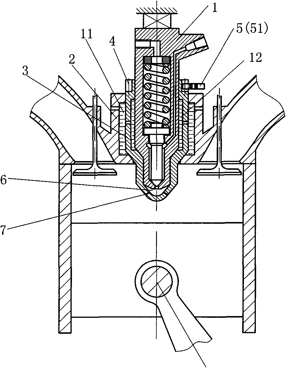
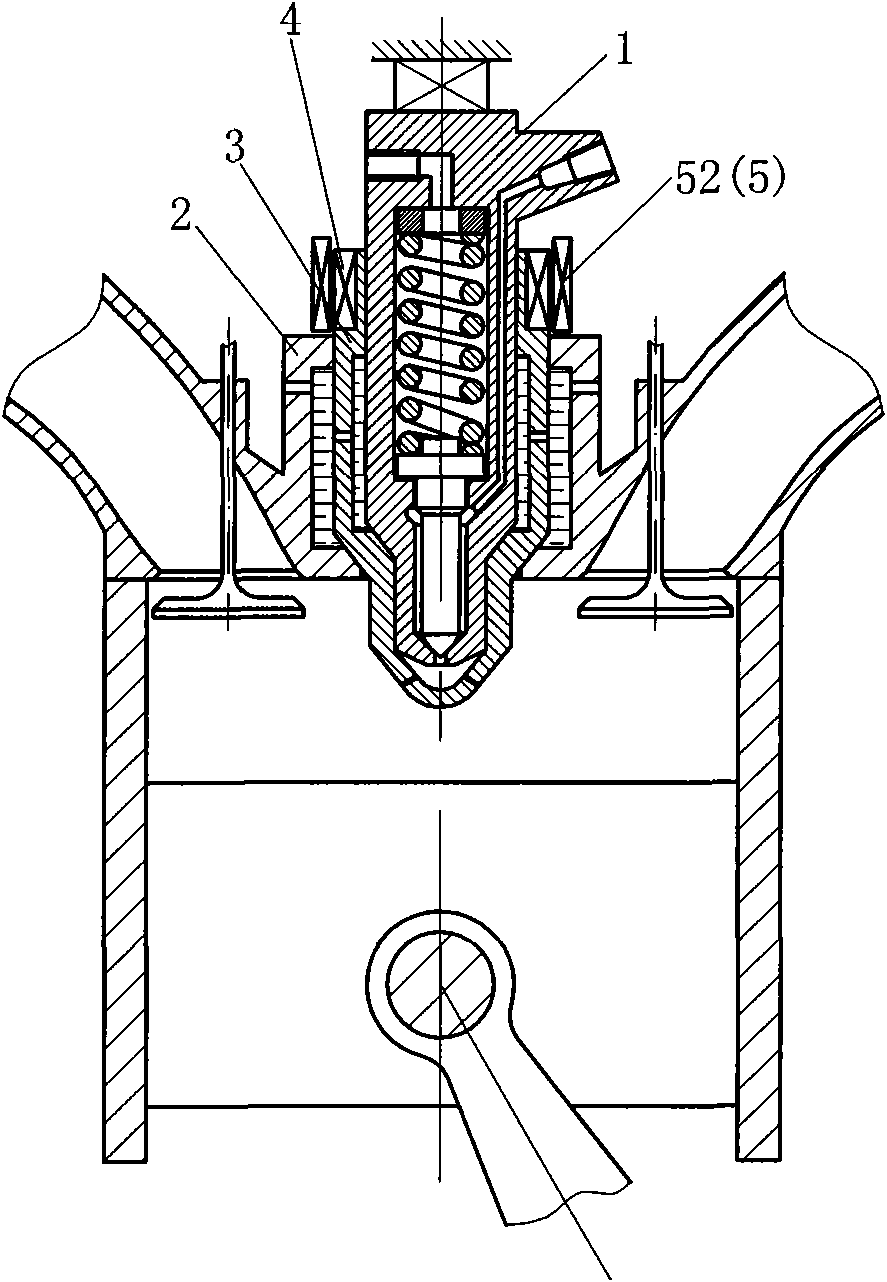
[0030] Such as figure 1 An outer-rotor full-range fuel injector for an engine is shown, including a fuel injector 1 and a combustion chamber interface body 2, and a rotating injection housing 3 is arranged between the fuel injector 1 and the combustion chamber interface body 2 , the rotary injection housing 3 is respectively in rotary and sealing contact with the fuel injector 1 and the combustion chamber interface body 2, and a rotary driving structure 4 is arranged on the rotary injection housing 3, and the rotary driving structure 4 is controlled by The drive device 5 is controlled.

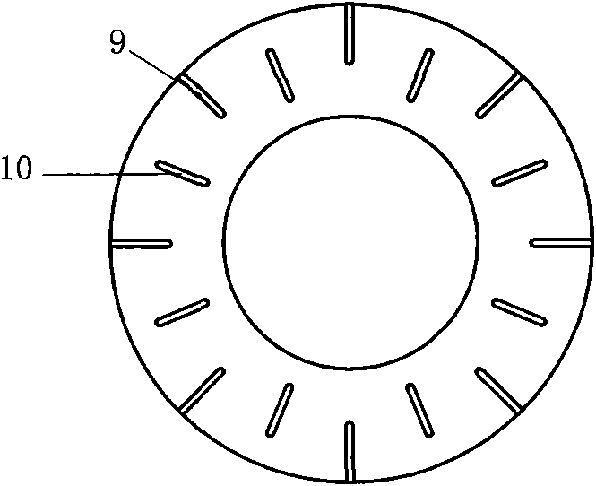
[0031] A fuel distribution area 6 is provided on the lower part of the rotating injection housing 3, and the fuel distribution area communicates with the fuel injection hole of the fuel injector 1, and an injection hole 7 is arranged on the outer wall of the fuel d...


PUM


Abstract

The invention discloses an outer rotor global fuel injector used for an engine, comprising a fuel injector (1) and a combustion chamber interface body (2). The outer rotor global fuel injector is characterized in that a rotating injection shell (3) is arranged between the fuel injector (1) and the combustion chamber interface body (2) and respectively contacted with the fuel injector (1) and the combustion chamber interface body (2) in a rotating and sealing mode; and a rotating driving structure (4) is arranged on the rotating injection shell (3) and controlled by a driving device (5). The outer rotor global fuel injector can realize mixing of fuel and air in the global area of a combustion chamber or an air cylinder and improve the combustion performance of the mixed gas, thus improving the efficiency and environmental protection of the engine.

Description

technical field [0001] The invention relates to the field of engines. Background technique [0002] The engine fuel injection device and its technology are very important to the efficiency and environmental protection of the engine. Therefore, there are many researches and products in this field. However, the fundamental problem of fuel injection is how to improve the mixing degree of fuel and air and realize the adjustability of injection timing and fuel injection quantity. So far, the fuel injection technology has adopted the fixed fuel injection technology. Since the fuel injection will form a cone-shaped oil mist, a blank space with no oil mist or little oil mist will be formed between different cone-shaped oil mist. , it is obvious that the air and fuel in the empty space are not mixed well or not mixed at all, which affects the combustion of the mixture in the combustion chamber. Usually, in order to reduce and eliminate this blank space, high atomization injection t...

Claims


Application Information

Patent Timeline
Patent Type & Authority Applications(China)
IPC IPC(8): F02M59/12F02M51/00F02M47/00
Inventor 靳北彪
Owner 靳北彪
Why Eureka
Try Eureka