Magnetic pump

A magnetic pump and pump cover technology, applied in the direction of pumps, pump devices, pump components, etc., can solve problems such as unsmooth backflow, damage to the isolation sleeve, and large axial pressure, so as to achieve smooth circulation, improve service life, and adaptability strong effect

Active Publication Date: 2009-10-14
DANDONG COLOSSUS GROUP
View PDF0 Cites 28 Cited by
  • Summary
  • Abstract
  • Description
  • Claims
  • Application Information

AI Technical Summary

Problems solved by technology

The existing technology is to connect the high-pressure area in the pump cavity with the inner cavity of the isolation sleeve, and the medium in the isolation sleeve mainly flows back to the low-pressure part of the center of the pump cavity through a through hole in the center of the shaft end of the pump shaft, and part of the medium passes through the sliding bearing. The pores on the top flow back to the low-pressure area in the center of the pump chamber, and the medium in the high-pressure area in the pump chamber flows in to cool the eddy current heat generated by the spacer sleeve in the inner cavity of the rotor and the sliding bearing. The disadvantage is that the medium heated by the spacer sleeve is The return hole opened in the center hole of the pump shaft end flows back to the low-pressure area at the entrance of the pump chamber, which is likely to cause gasification of the medium, pump vacuum and cavitation, and affect the normal operation of the pump. Once the pump is pumped out, the inner cavity of the rotor will not be cooled by the medium , the magnetic rotor overheats, which will burn the equipment; in addition, since the cooling medium in the isolation sleeve is returned from the center hole of the shaft, the return flow of the medium needs to resist the centrifugal force of the inner magnetic rotor to flow to the return hole on the center of the pump shaft, which does not meet the flow requirements. Regularity, so the backflow is not smooth, and the particles such as sand in the cooling medium are affected by the centrifugal force of the inner magnetic rotor, and it is not easy to flow into the center of the pump shaft, but gather around the bottom of the isolation sleeve, which will wear the bottom of the isolation sleeve and cause rinsing. At the same time, the medium will cause cavitation to the isolation sleeve near the pump shaft, which will cause cavitation and perforation of the isolation sleeve, which will easily cause damage to the isolation sleeve, increase maintenance, and affect production and normal work.
In addition, due to the different pressures on the left and right sides of the impeller in the pump chamber, the axial pressure of the impeller acting on the pump shaft is relatively large, the axial force balance of the pump shaft is not good, and the pump bearing is subjected to a large axial force, especially When starting up, there will be a pressure shock, which will easily cause the wear of the pump shaft sliding bearing and the thrust plate sliding bearing

Method used


Image

  • Magnetic pump
  • Magnetic pump
  • Magnetic pump

Examples


Embodiment Construction

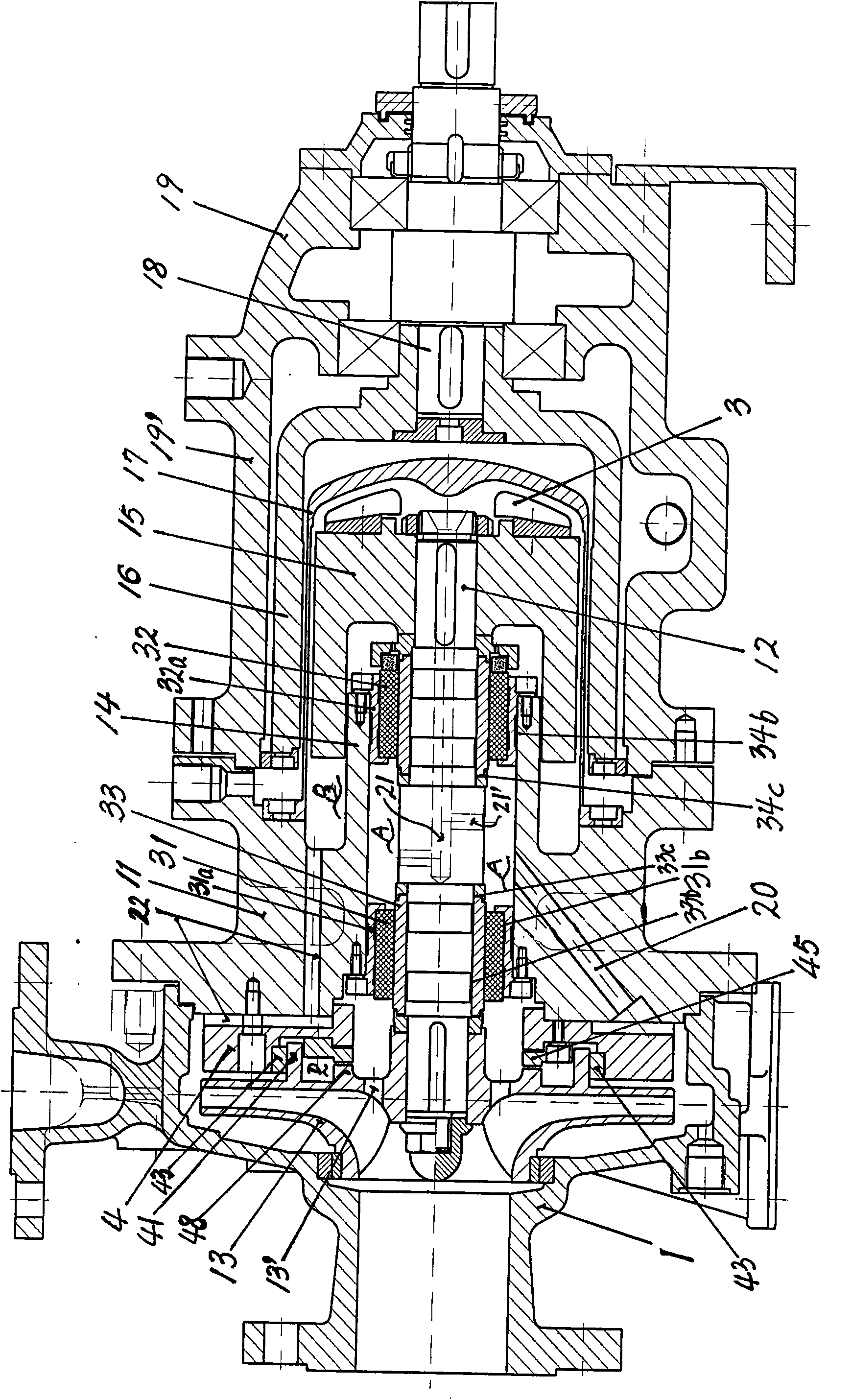
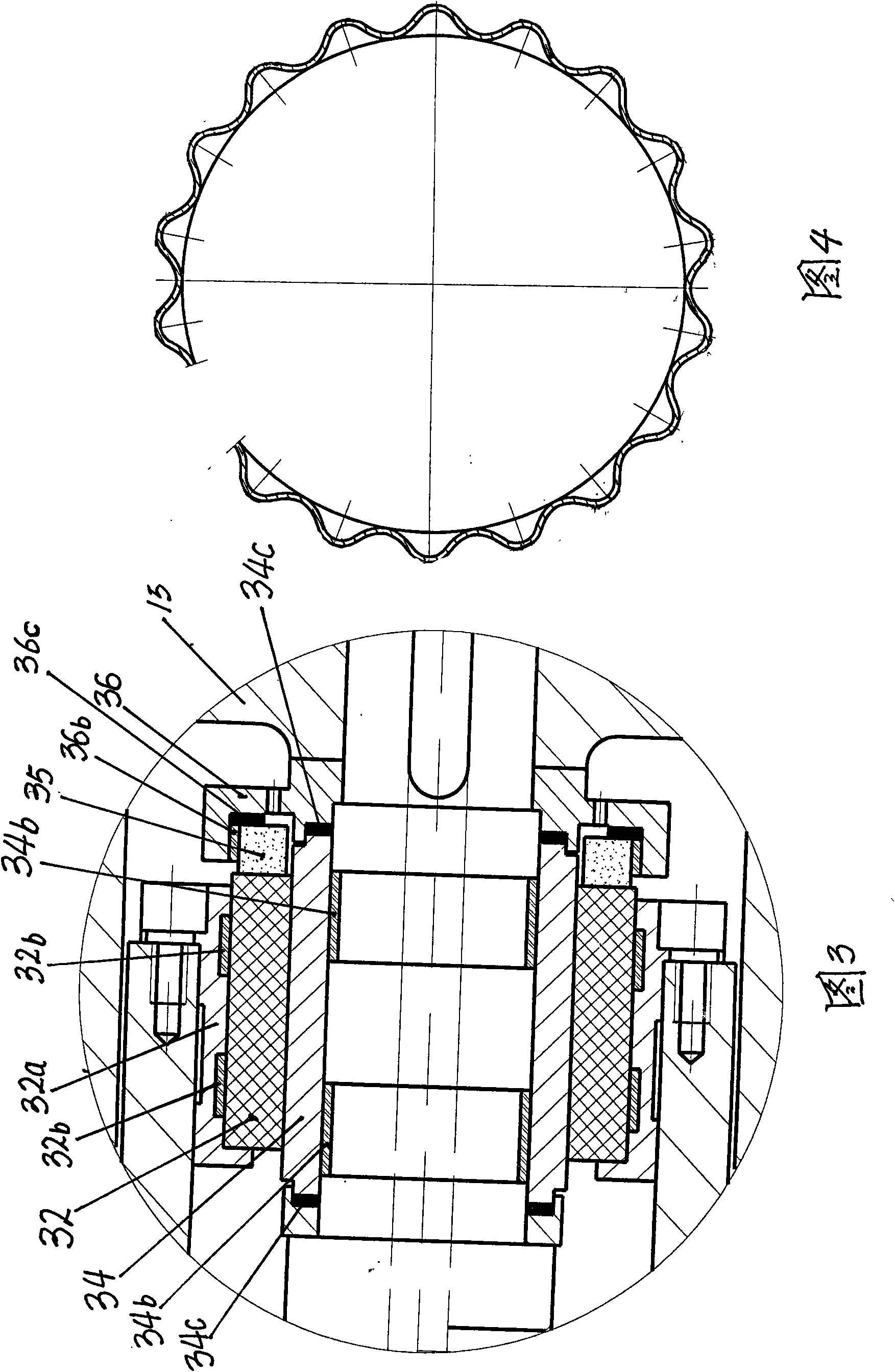
[0014] The present invention includes a pump body 1, a pump cover 11, a pump shaft 12, an impeller 13, an inner magnetic rotor 15, an outer magnetic rotor 16, an isolation sleeve 17, a drive shaft 18, a drive shaft bearing housing 19, and the pump shaft 12 passes through a sliding bearing 31 , 32 are installed in rotation with the bearing housing 14 on the pump cover, the inner magnetic rotor 15 is fixedly installed on the shaft end of the pump shaft 12, the outer magnetic rotor 16 is fixedly installed on the shaft end of the drive shaft 18, the inner magnetic rotor 15 and the outer magnetic rotor A spacer 17 is arranged between the magnetic rotors 16, and the spacer 17 is sealed and fixedly connected with the pump cover 11, and the drive shaft bearing box 19 is docked and fixedly connected with the pump cover 11 through its connecting frame 19'. It is characterized in that the high pressure on the pump cover 11 There is a coolant medium inlet hole 20 between the inner ring of ...


PUM


Abstract

The invention relates to a magnetic pump, which comprises a pump body, a pump bonnet, a pump spindle, an impeller, an internal magnetic rotor, an external magnetic rotor, a separation sleeve, a driving shaft, a driving shaft bearing box; the cooling medium of the rotor internal cavity thereof is drawn into from the high pressure area of the pump chamber and reflows; the medium smoothly flow and does not generate gasification and evacuation to the pump chamber; particulate matters such as sand grains and the like in the medium do not generate aggregation to wear the bottom of the separation sleeve around the bottom of the separation sleeve; a pressure balancing cavity (D designed between the rear side of the impeller (13) and the pump bonnet to automatically balance the axial balancing force of the impeller on the pump spindle (12) and cause the pump spindle to bear the minimum axial acting force; a corrugation cushion collar is arranged on a sliding bearing and a sliding bearing bush to play the elastic protection and cause that the performance of the pump is be increased, the pump is safe in utilization and has long service life.

Description

technical field [0001] The present invention relates to a magnetic pump. Background technique [0002] The magnetic pump is a pump in which the outer magnetic rotor and the inner magnetic rotor cooperate to drive the inner magnetic rotor to rotate through magnetic force, and the inner magnetic rotor drives the pump shaft to rotate, so that the impeller rotor on the pump shaft in the pump body rotates to work. The magnetic pump is provided with an isolation sleeve between the inner magnetic rotor and the outer magnetic rotor to form a sealed cavity, which seals the main shaft and the inner magnetic rotor in the sealed cavity. and inner magnetic rotor part for cooling. The existing technology is to connect the high-pressure area in the pump cavity with the inner cavity of the isolation sleeve, and the medium in the isolation sleeve mainly flows back to the low-pressure part of the center of the pump cavity through a through hole in the center of the shaft end of the pump shaf...

Claims


Application Information

Patent Timeline
Patent Type & Authority Applications(China)
IPC IPC(8): F04D13/02F04D29/58F04D29/22F04D29/046
Inventor 于华宇萧建邦靖永毅杨德乾栾晓颖柴鹏举
Owner DANDONG COLOSSUS GROUP
Why Eureka
Try Eureka