Switching magnetic valve

A technology for switching solenoid valves and solenoid armatures, applied in valve details, valve devices, control valves and air release valves, etc., can solve problems such as reducing efficiency, interfering with magnetic flux, and slow response time.

Inactive Publication Date: 2009-10-14
WABCO GMBH
View PDF4 Cites 21 Cited by
  • Summary
  • Abstract
  • Description
  • Claims
  • Application Information

AI Technical Summary

Problems solved by technology

Another disadvantage is that the spring for returning the solenoid armature disturbs the magnetic flux between the coil and the solenoid armature, thereby reducing the effici

Method used


Image

  • Switching magnetic valve
  • Switching magnetic valve
  • Switching magnetic valve

Examples


Embodiment Construction

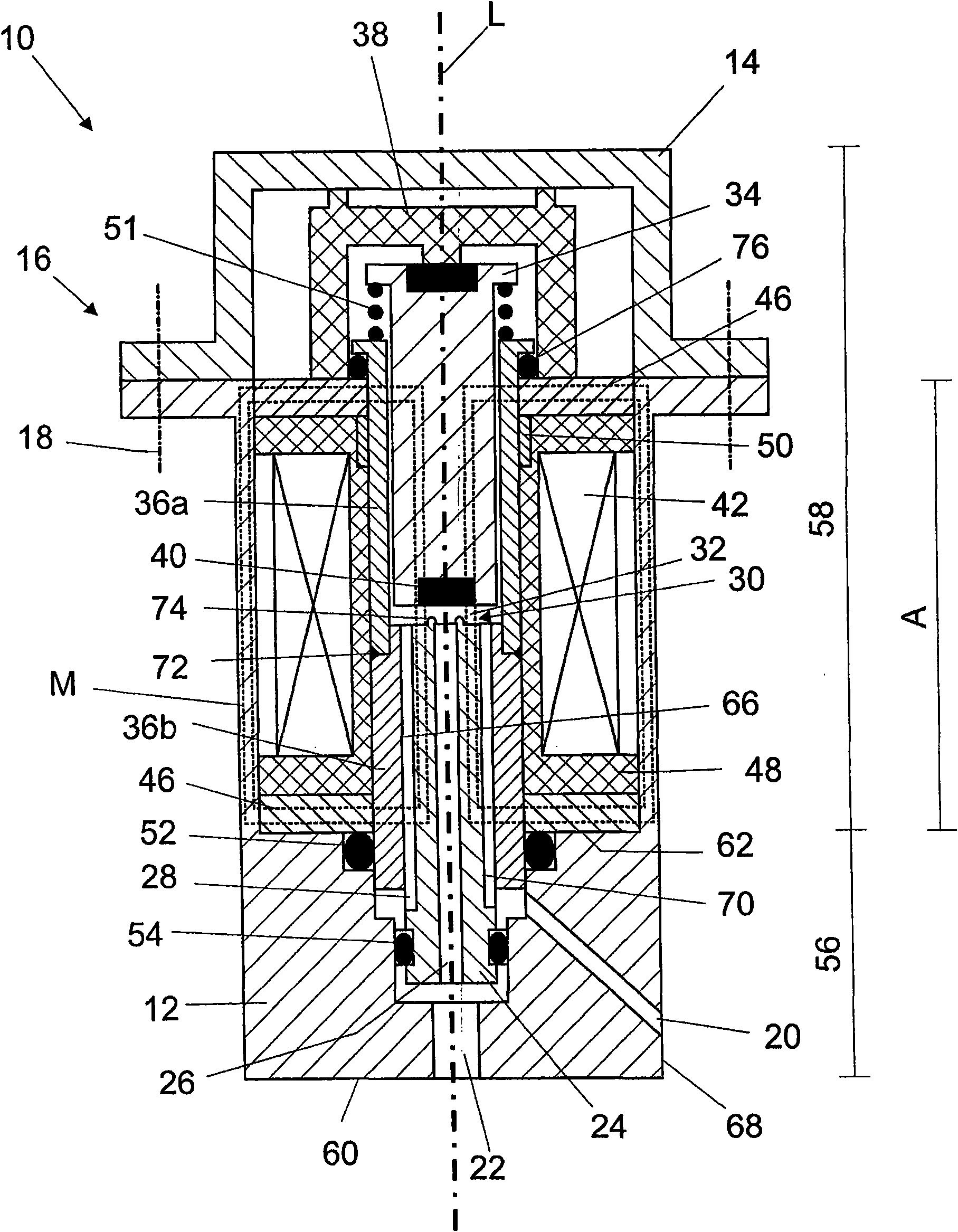
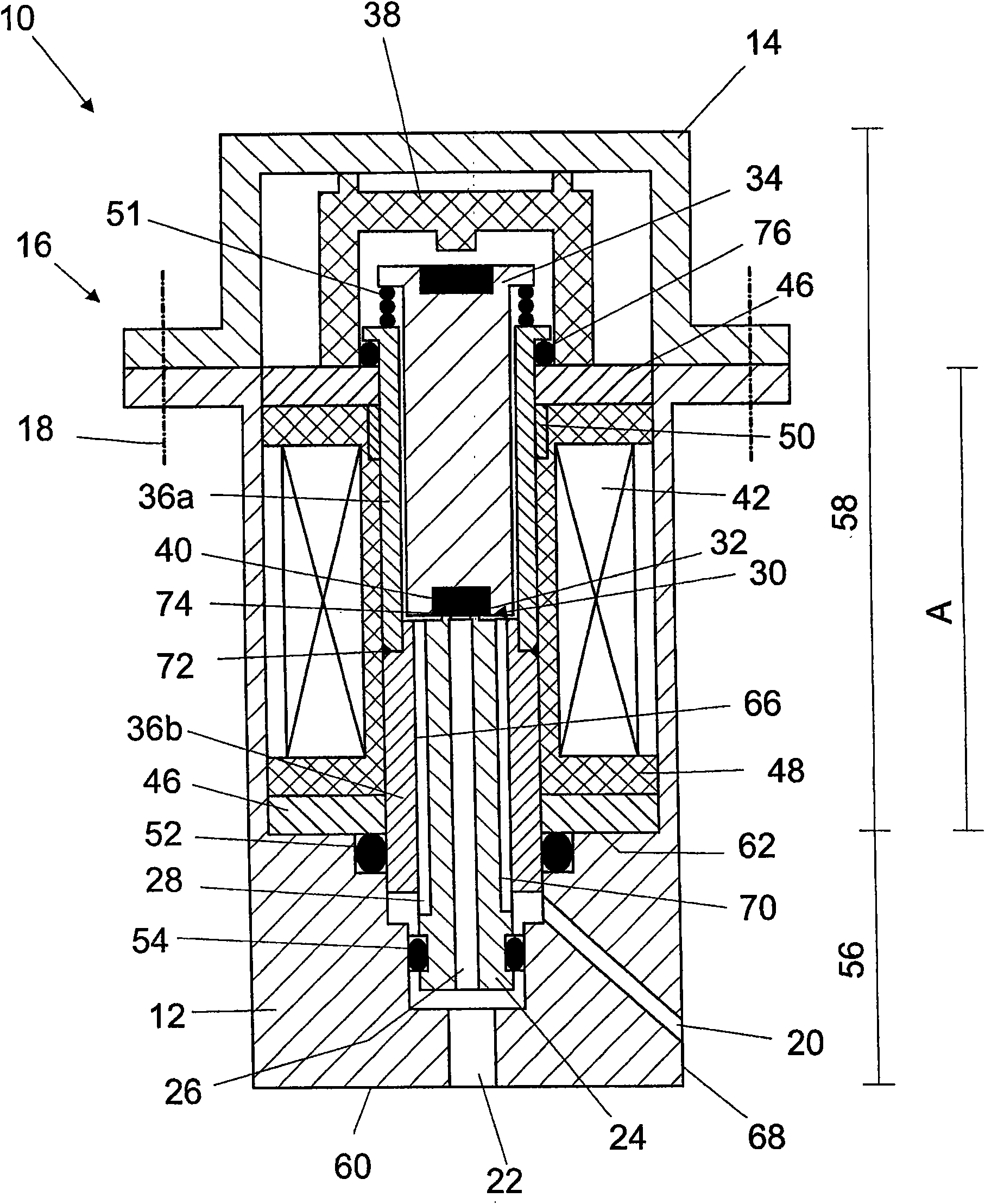
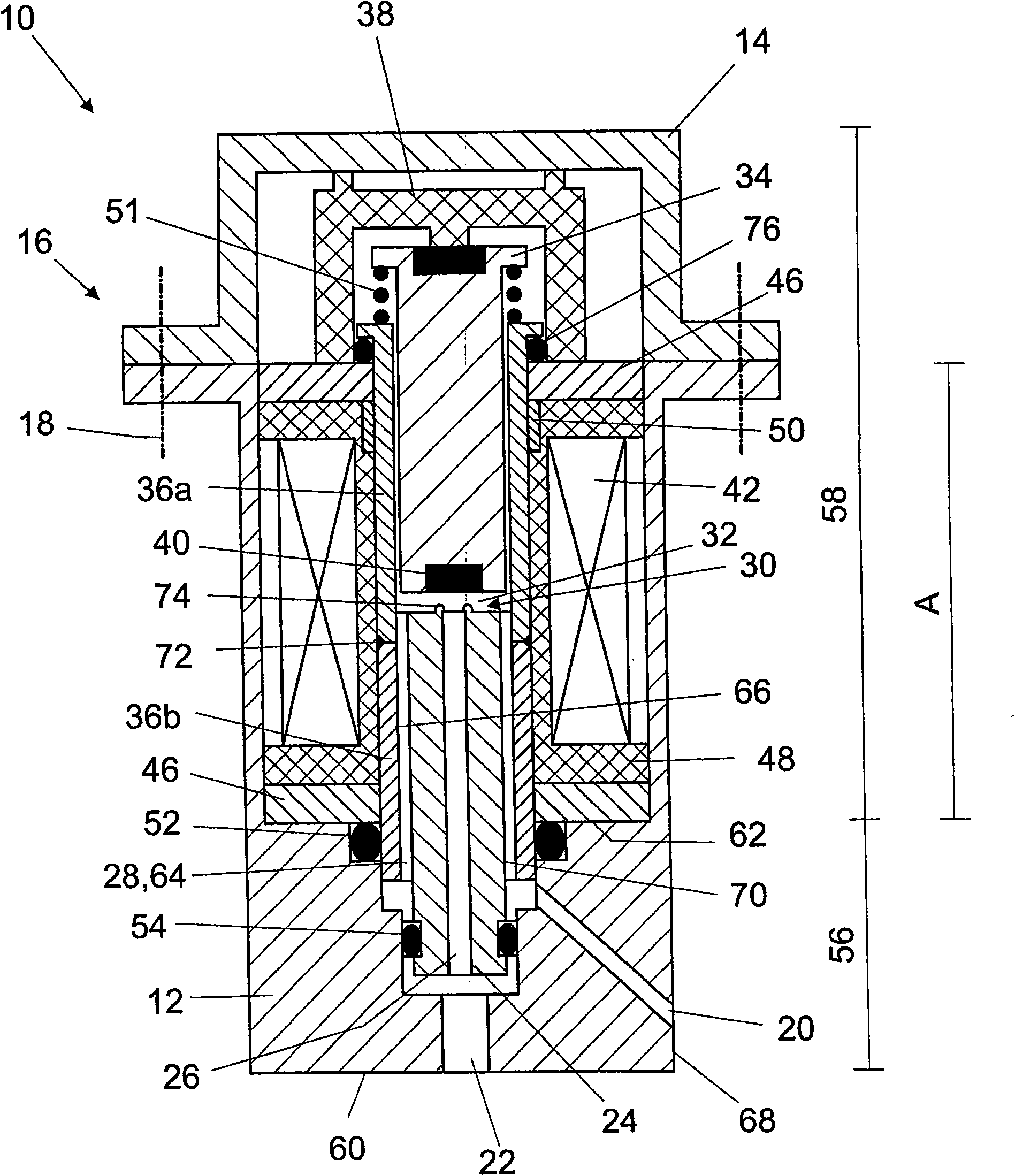
[0024] exist figure 1 and 2 The switching solenoid valve 10 shown in includes a housing 12 , preferably made of a magnetizable material such as iron, which can be selectively opened by means of a cover or bow 14 . In the example shown, the bracket 14 is connected to the housing 12 via a flange connection 16 , where screws 18 are used as fastening means. Other ways of fastening the bracket 14 to the housing 12 are also possible. The housing 12 has a first channel 20 and a second channel 22 for introducing compressed air into the interior of the switching solenoid valve 10 or leading compressed air out of the interior of the switching solenoid valve 10 . A valve core 24 is arranged inside the housing 12 , and the valve core 24 communicates with the first channel 20 and the second channel 22 . In addition, the valve element 24 has a bore 26 on which one or more gaps 28 are additionally located, which form a flow channel 28 through which compressed air can be directed in the di...


PUM


Abstract

The present invention relates to a switch magnetic valve, which is taken as a pre-control valve to generate and control pressure in vehicle pneumatic braking system, wherein the switch magnetic valve comprises a first passage, used for introducing compressed-air into the switch magnetic valve or export compressed-air from the switch magnetic valve; a second passage, used for introducing compressed-air into the switch magnetic valve or export compressed-air from the switch magnetic valve; a valve chamber including a valve seat for selectively release and break off compressed-air stream; and a valve core, provided with an outer housing surface and a hole used let the compressed-air pass through. According to the invention, the valve chamber (32) is provided with a flow path (28); the flow path (28) neighbors with housing surface (70) of the valve core (24); the flow path (28) is formed by at least one gap on housing surface (70) of the valve core (24) in preference.

Description

technical field [0001] The invention relates to an on-off solenoid valve, in particular as a pre-control valve for generating and controlling a control pressure in a compressed air brake system of a vehicle, the on-off solenoid valve comprising a first channel for introducing compressed air into the on-off solenoid valve or Deriving compressed air from the on-off solenoid valve; a second channel for introducing compressed air into the on-off solenoid valve or deriving compressed air from the on-off solenoid valve; a valve chamber including a valve seat for selectively releasing and interrupting the flow of compressed air; And a valve core having an outer shell surface and a through hole for the passage of compressed air. Background technique [0002] Pilot control valves are used for pressure actuation of larger valves such as directional valves of brake systems. The control of the control pressure can be carried out not only in a continuous manner but also in a stepped man...

Claims


Application Information

Patent Timeline
IPC IPC(8): F16K31/06
CPCB60T13/683B60T15/027F16K31/0658B60T8/362
Inventor 英戈·富尔曼维尔弗里德·门泽尔托马斯·穆勒卡尔-海因茨·里迪格-杰尼施朱安·罗维拉-雷法泰拉哈特姆特·沙普勒安德烈亚斯·泰希曼卡尔-海因茨·里迪格-杰尼施朱安·罗维拉-雷法泰拉
Owner WABCO GMBH
Why Eureka
Try Eureka